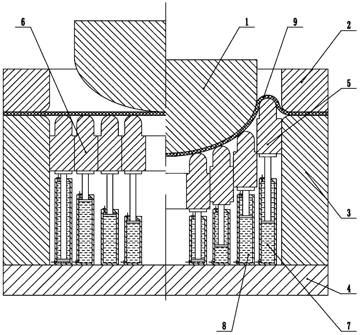
Forming device and method for large thin-wall curved-surface element

A curved surface and thin-walled technology, which is applied in the field of thin-walled curved surface parts manufacturing equipment, can solve problems such as easy wrinkling, affecting reliability, and degradation of tissue performance, and achieve the effect of eliminating wrinkling

Active Publication Date: 2019-10-15
HARBIN INST OF TECH
View PDF11 Cites 4 Cited by
  • Summary
  • Abstract
  • Description
  • Claims
  • Application Information

AI Technical Summary

Problems solved by technology

The above-mentioned head is usually manufactured by the thick plate spinning process, but there are a series of problems: it is easy to wrinkle, and the thickness of the curved surface part with a diameter of 3000mm cannot be less than 30mm, otherwise the wrinkle defect cannot be controlled, and the subsequent machining and chemical milling remove the excess thickness ;The heating in the spinning process is difficult to control accurately, resulting in a decrease in tissue performance and affecting reliability; the spinning efficiency is low, the loading path is complicated, the processing cycle is long, and the dimensional accuracy is poor, and large-scale high-precision parts require high rigidity and precision of spinning equipment , but Germany and other countries restrict

Method used


Image

  • Forming device and method for large thin-wall curved-surface element

Examples


Example Embodiment

[0025] The technical solutions in the embodiments of the present invention will be clearly and completely described below in conjunction with the accompanying drawings in the embodiments of the present invention. Obviously, the described embodiments are only a part of the embodiments of the present invention, rather than all the embodiments. Based on the embodiments of the present invention, all other embodiments obtained by those of ordinary skill in the art without creative work shall fall within the protection scope of the present invention.

[0026] The purpose of the present invention is to provide a large-scale thin-walled curved part forming device and method to solve the above-mentioned problems in the prior art, eliminate wrinkles in the suspended area of ​​the large-scale thin-walled curved part, and improve the forming quality.

[0027] In order to make the above objectives, features and advantages of the present invention more obvious and understandable, the present inve...


PUM


Abstract

The invention discloses a forming device for a large thin-wall curved-surface element. The forming device for the large thin-wall curved-surface element comprises a convex die, a blank holder, a concave die, a lower die plate, a first annular sleeve and a second annular sleeve, wherein the first annular sleeve is connected with a first drive oil cylinder; the first drive oil cylinder is capable ofdriving the first annular sleeve to move up and down; the inner diameter of the concave die is greater than the outer diameter of the convex die; the first annular sleeve is arranged in a gap betweenthe convex die and the concave die; the second annular sleeve is arranged at the bottom of the convex die; the first annular sleeve is arranged outside the second annular sleeve; the second annular sleeve is connected with a second drive oil cylinder; the second drive oil cylinder is capable of driving the second annular sleeve to move up and down; each of the first drive oil cylinder and the second drive oil cylinder is connected with a hydraulic system; and one surface facing the convex die, of each of the first annular sleeve and the second annular sleeve is an arc-shaped surface. The invention further provides a forming method for a large thin-wall curved-surface element. By virtue of the forming device, a draw bead is formed in a suspended area of a deformed plate blank, so that thewrinkles of the suspended area are eliminated.

Description

technical field [0001] The invention relates to the technical field of manufacturing equipment for thin-walled curved surface parts, in particular to a forming device and method for large-scale thin-walled curved surface parts. Background technique [0002] In the pressure vessels in the aerospace and petrochemical fields, the combined welding of the head and the barrel section constitutes the main structure of the pressure vessel, and this structural form is widely used. The shape of the head usually adopts spherical or semi-ellipsoidal surface, and the diameter of large curved surface parts is generally more than 3000mm, which is a large thin-walled complex curved plate part. The above-mentioned head is usually manufactured by the thick plate spinning process, but there are a series of problems: it is easy to wrinkle, and the thickness of the curved surface part with a diameter of 3000mm cannot be less than 30mm, otherwise the wrinkle defect cannot be controlled, and the s...

Claims


Application Information

Patent Timeline
IPC IPC(8): B21D22/22B21D22/24B21D37/10
CPCB21D22/22B21D22/24B21D37/10B21D37/02B21D22/205B21D51/08B21D11/22B21D22/06B21D24/08B21D43/003
Inventor 徐永超苑世剑
Owner HARBIN INST OF TECH
Why Eureka
Try Eureka