Deceleration cutting control method and control device

A technology of control method and control device, which is applied in the direction of program control, general control system, control/adjustment system, etc., can solve the problems of poor pole piece cutting accuracy, influence on stability, influence on cell yield, etc., and improve deceleration efficiency , Shorten the deceleration time, and the effect of cutting control is simple and easy

Active Publication Date: 2019-10-15
GUANGDONG LYRIC ROBOT INTELLIGENT AUTOMATION CO LTD
View PDF6 Cites 1 Cited by
  • Summary
  • Abstract
  • Description
  • Claims
  • Application Information

AI Technical Summary

Problems solved by technology

During the operation of the automatic winding machine, the operating speed of the positive and negative electrodes is usually uncontrollable, and the operating speed of the positive and negative electrodes directly affects the stability of the oper

Method used


Image

  • Deceleration cutting control method and control device
  • Deceleration cutting control method and control device

Examples


Embodiment 1

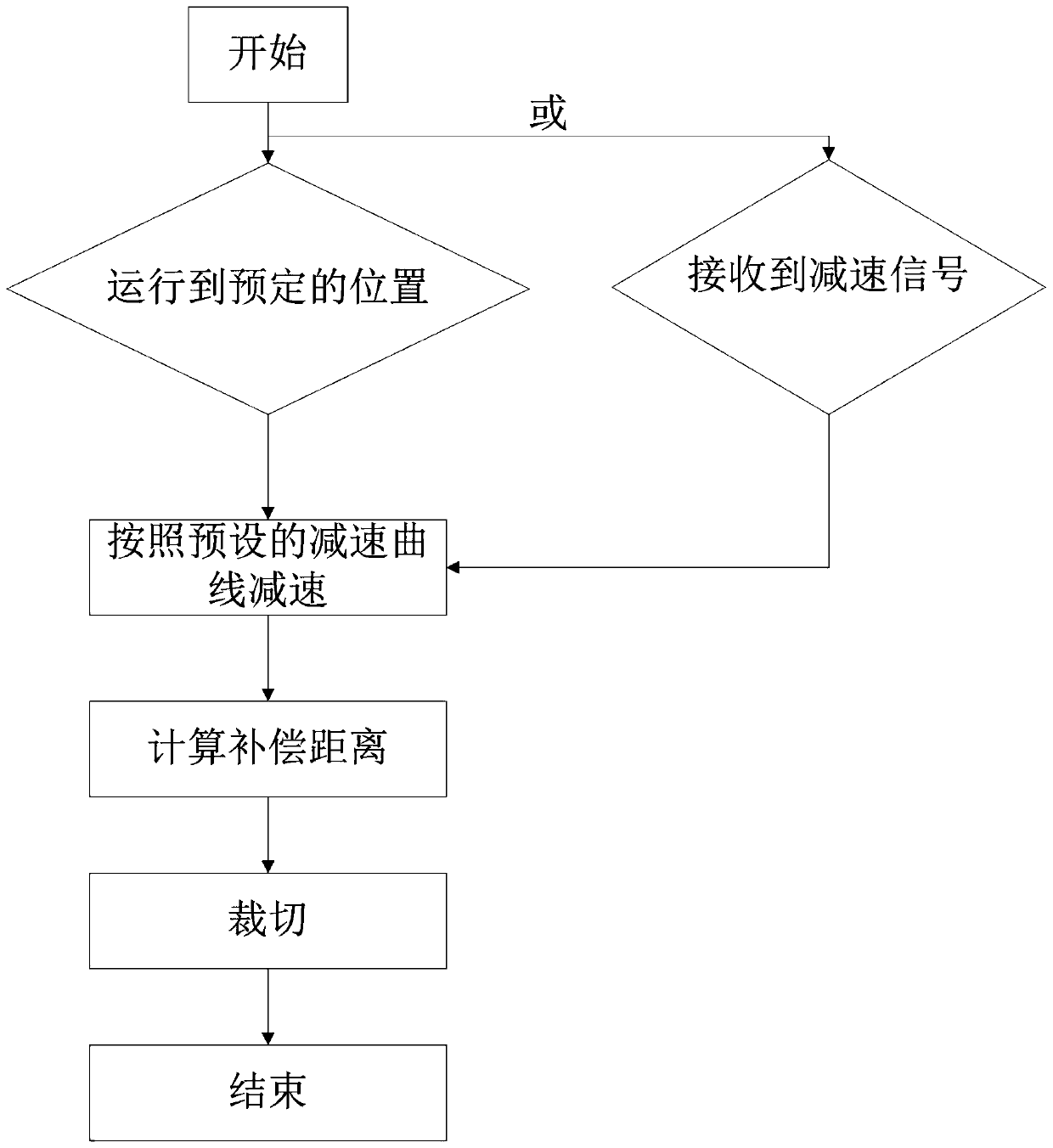
[0029] This embodiment provides a deceleration cutting control method, please refer to figure 1 , which is a flow chart of the deceleration and cutting control method in this embodiment. The deceleration and cutting control method of this embodiment includes: when the product to be cut runs to a predetermined position, or receives a deceleration signal, the product to be cut is decelerated according to a preset deceleration curve; The set deceleration curve completes the deceleration, and the product to be cut is cut. That is to say, when the cutting product moves to the predetermined position and any one of the conditions of receiving the deceleration signal is met, the product to be cut will decelerate according to the preset deceleration curve. For example, when the cutting product moves to the predetermined position but If the deceleration signal is not received, the product to be cut will decelerate according to the preset deceleration curve, or, when the deceleration si...

Embodiment 2

[0036] This embodiment provides a deceleration and cutting control device, which includes a conveying element, a detection element, a sensor, a controller, and a cutting element. The conveying part is used to convey the products to be cut, and the conveying part includes a main drive motor, a winding motor and a plurality of rollers. The detection element is used to detect the running state of the conveying piece. The detection element includes an encoder, which is installed on one of the rollers. The encoder measures the angle or number of turns of the roller, and outputs a pulse signal according to the measured angle or number of turns. The sensor is used to sense the product to be cut and emit a deceleration signal. The sensor can be a deceleration photoelectric sensor. When the sensor detects that the product to be cut enters the sensing range, it emits a deceleration signal.

[0037] The controller judges whether the product to be cut runs to the predetermined position or...


PUM


Abstract

The invention discloses a deceleration cutting control method and control device. The deceleration cutting control method comprises the steps that when a product to be cut runs to the preset positionor receives a deceleration signal, the product to be cut is decelerated according to a preset deceleration curve; and when the product to be cut finishes deceleration according to the preset deceleration curve, the product to be cut is cut. The control device comprises a conveying piece, a detection element, a sensor, a controller and a cutting piece. That the product to be cut runs to the presetposition or receives the deceleration signal is adopted as a control signal for decelerating the product to be cut, that is, the product to be cut is decelerated according to the preset deceleration curve as long as any one of the signal that the product to be cut runs to the preset position or the deceleration signal is received is received, and the product to be cut is decelerated according to the preset deceleration curve; and the deceleration curve is preset in advance, so that the preset deceleration curve is flexibly planned, the product to be cut is decelerated according to the deceleration curve, the deceleration time is shortened, and the deceleration efficiency is improved.

Description

technical field [0001] The present application relates to the technical field of cutting control, and in particular, relates to a deceleration cutting control method and a control device. Background technique [0002] In the process of conveying the products to be cut for cutting, it is usually necessary to consider the influence of the running speed of the products to be cut on the cutting accuracy, so as to ensure the cutting quality. For example, in the production process of lithium battery cells, it is usually necessary to use a fully automatic winding machine to make the entire roll of positive and negative electrodes and separators into cells by winding. The main action process of the automatic winding machine includes Loading, pre-rolling, winding of positive and negative electrode sheets and separators, cutting of electrode sheets and separators, changing stations, sticking tapes and cutting materials, etc. During the operation of the automatic winding machine, the ...

Claims


Application Information

Patent Timeline
IPC IPC(8): B65H35/00
CPCB65H35/0073B65H2511/22B65H2513/10B65H2220/01B65H2220/02B26D5/00B26D5/26B26D5/007B26D5/32B26D5/34G05B19/4166
Inventor 周俊杰周明浪蔡文杰许天锋李峰
Owner GUANGDONG LYRIC ROBOT INTELLIGENT AUTOMATION CO LTD
Why Eureka
Try Eureka