

Heavy oil hybrid power cooling system based on variable pitch propeller
A variable-pitch propeller and hybrid technology, applied in the cooling system of the power plant, propellers, aircraft parts, etc., can solve the problems of difficulty in increasing the speed, the effect of air cooling is not obvious, and the efficiency of the blades is reduced, so as to achieve cooling, Simple and fast distributed, optimized management effect
- Summary
- Abstract
- Description
- Claims
- Application Information
AI Technical Summary
Problems solved by technology
Method used
Image

Examples
Embodiment Construction
[0030] The present invention will now be further described in detail in conjunction with the accompanying drawings and embodiments. These drawings are all simplified schematic diagrams, only illustrating the basic structure of the present invention in a schematic manner, so it only shows the composition related to the present invention.
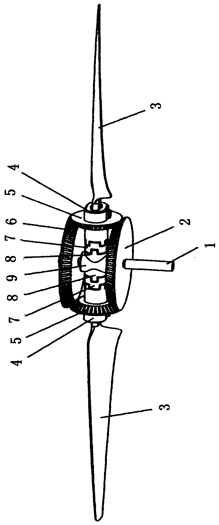
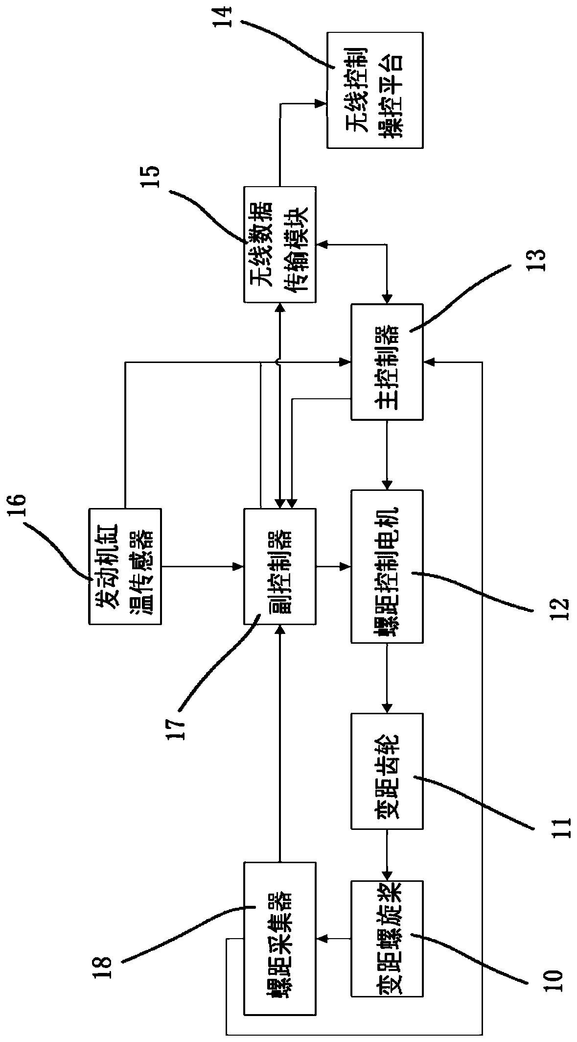
[0031] Such as figure 1 and figure 2 As shown, the heavy oil hybrid cooling system based on variable pitch propellers includes: a pitch control device, a control platform 14, a main controller 13 wirelessly connected with the control platform 14; the pitch control device includes a variable pitch propeller 10, a main controller 13. Pitch collector 18; the pitch collector 18 is installed on both sides of the blade 3 of the variable pitch propeller 10, and the pitch collector 18 is used to collect the real-time pitch value of the variable pitch propeller 10; the pitch collector The device 18 is electrically connected with the main controller ...
PUM
 Abstract
Description
Claims
Application Information