
Excavation and supporting anchor machine

A windlass and main body technology, which is applied in the installation of bolts, mining equipment, earthwork drilling and mining, etc., can solve the problems of low safety factor in the work site of support personnel, increase the load of the cutting part, and high labor intensity of personnel, etc., to achieve The effect of improving quality and construction efficiency, improving construction quality and efficiency, and reducing labor intensity

Pending Publication Date: 2019-10-18
欧玉金
View PDF2 Cites 5 Cited by
  • Summary
  • Abstract
  • Description
  • Claims
  • Application Information

AI Technical Summary

Problems solved by technology

[0003] The current method of tunneling, mining, especially coal mine tunneling and bolting is that the roadheader generally does not exceed 2 meters in advance, and the backstop is stopped, and the support personnel carry the movement or hydraulic drilling rig and support materials to the tunnel. The front end of the machine is supported by the roof and two groups of bolts. The support personnel work under the string-type temporary support with low support force. Such a cycle operation will result in high labor intensity, low construction efficiency and safety factor of the support personnel's work site. Low
In roadway excavation and bolting, the operating rate of the roadheader is only about 30%, that is, two-thirds of the time is used for artificial bolting. The root cause is that the current roadheader has a single function and lacks A high-efficiency roadheader with multiple functions
[0004] In recent years, there are anchor mounting mechanisms installed on both sides of the front end of the cutting arm of the roadheader, and a roof frame is installed above the cutting arm, such as the publication number CN107420101A, which has a cutting part with anchor mounting and supporting functions, although it reduces the number of operators. Part of the labor intensity, but when the roadheader is working, the cutting arm vibrates very much, the anchor and jacking mechanism are easily damaged, and the load on the cutting part is increased, which reduces the service life of the roadheader
[0005] There is also a top bolter installed on the front side of the roadheader body part, and a side bolter installed on the top surface of the rear part of the body, such as the announcement number CN102364053B bolter, although it solves the problem that the bolter is installed on the side of the cutting arm , the cutting arm vibration damages the bolter when the roadheader is working, but the top bolter cannot perform roadway side bolt support, and the side bolter cannot perform roadway roof bolt support; although the side bolter can Lifting, but the side bolter is located on the top surface of the rear part of the main body installed on the walking part. When the side bolter is at the lowest position for side bolting, the side bolting near the bottom plate cannot be constructed.
The distance between the temporary support connected to the walking track frame and the front end of the cutting part is long, the longitudinal distance of the supporting roadway is short, and the roadway roof has a long distance in an empty state without any support, which is not conducive to the safety management of the roadway roof

Method used


Image

  • Excavation and supporting anchor machine
  • Excavation and supporting anchor machine
  • Excavation and supporting anchor machine

Examples


Embodiment Construction

[0019] Attached below Figure 1-7 The present invention is further described.

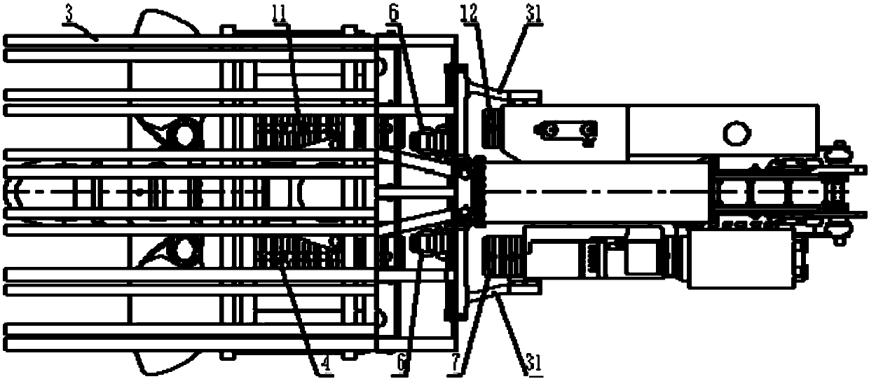
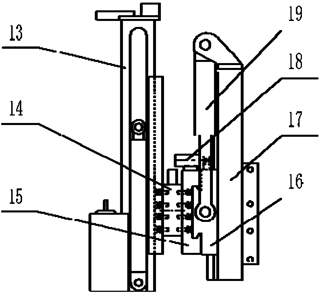
[0020] Such as Figure 1~2 As shown, the present invention provides a bolter digger comprising a cutting part 1 hinged at the front end of the body part 5, a left front running part 4, a left rear running part 7, a right front running part 11, and a right rear running part 12 mounted on the body part 5 on both sides, the shovel part 2 is hinged with the front end of the body part 5 under the cutting part 1, and the drill and anchor device 6 is respectively installed between the left front running part 4 and the left rear running part 7 and between the right front running part 11 and the right rear running part 12 and connected with the body part 5, the support frame 31 is connected with the slide rail frame 17 and connected with the left rear and right rear walking parts respectively, the transportation part 10 is installed on the body part 5, and the gantry type temporary support device 3 base is...


PUM


Abstract

The invention provides an excavation and supporting anchor machine which solves the problems of low excavating efficiency, low anchor pole supporting efficiency, low safety protection coefficient of anchor pole supporting workers, high labor intensity of personnel and the like of the prior art. The anchor machine is reasonable in structure and simple in installation and maintenance. Drilling anchor devices are arranged between left front and left rear walking parts and between right front and right rear walking parts. Each drilling anchor device has the functions of drilling a top plate and sides and mounting anchor poles on the top plate and the sides. The drilling anchor devices can cover all positions where the top plate and the sides need to be drilled and provided with the anchor poles. A gantry-type temporary supporting device can temporarily support the top plate just exposed after the excavation. The excavation and supporting anchor machine fully meets the requirements of coalmine roadway excavation and support, realizes the mechanized continuous operation of coal (rock) cutting, loading and transportation and anchor pole supporting of the top plate and the two sides in aroadway, and significantly improves the roadway excavation and supporting efficiency and the personnel safety protection coefficient.

Description

technical field [0001] The invention relates to an excavation and protection bolter suitable for roadway excavation and support of mines, tunnels, coal mines and related projects, in particular to a roadway coal (rock) cutting, shipment, temporary support for the newly exposed roof, roof and two It is a bolt digging and protecting machine for continuous operation of bolt support. [0002] technical background [0003] The current method of tunneling, mining, especially coal mine tunneling and bolting is that the roadheader generally does not exceed 2 meters in advance, and the backstop is stopped, and the support personnel carry the movement or hydraulic drilling rig and support materials to the tunnel. The front end of the machine is supported by the roof and two groups of bolts. The support personnel work under the string-type temporary support with low support force. Such a cycle operation will result in high labor intensity, low construction efficiency and safety factor o...

Claims


Application Information

Patent Timeline
IPC IPC(8): E21D20/00E21D9/10E21D15/44
CPCE21D20/003E21D9/10E21D15/44
Inventor 欧玉金
Owner 欧玉金
Learn More