Imprecise fault identification method for power grid completeness state information reconstruction
A state information and fault identification technology, applied to electrical components, circuit devices, AC network circuits, etc., can solve problems such as difficult state information, and achieve the effects of improving monitoring efficiency, strong theoretical foundation, and strong practicability
- Summary
- Abstract
- Description
- Claims
- Application Information
AI Technical Summary
Problems solved by technology
Method used
Image
Examples
Embodiment
[0047] For the convenience of description, the relevant technical terms appearing in the specific implementation are explained first:
[0048] WAMS (Wide-Area Measurement System): wide-area measurement system;
[0049] RTU (Remote Terminal Unit): remote terminal control system
[0050] PMU (Phasor Measurement Unit): power system synchrophasor measurement;
[0051] ODP (Optimal Device Placement): the optimal configuration of the device;
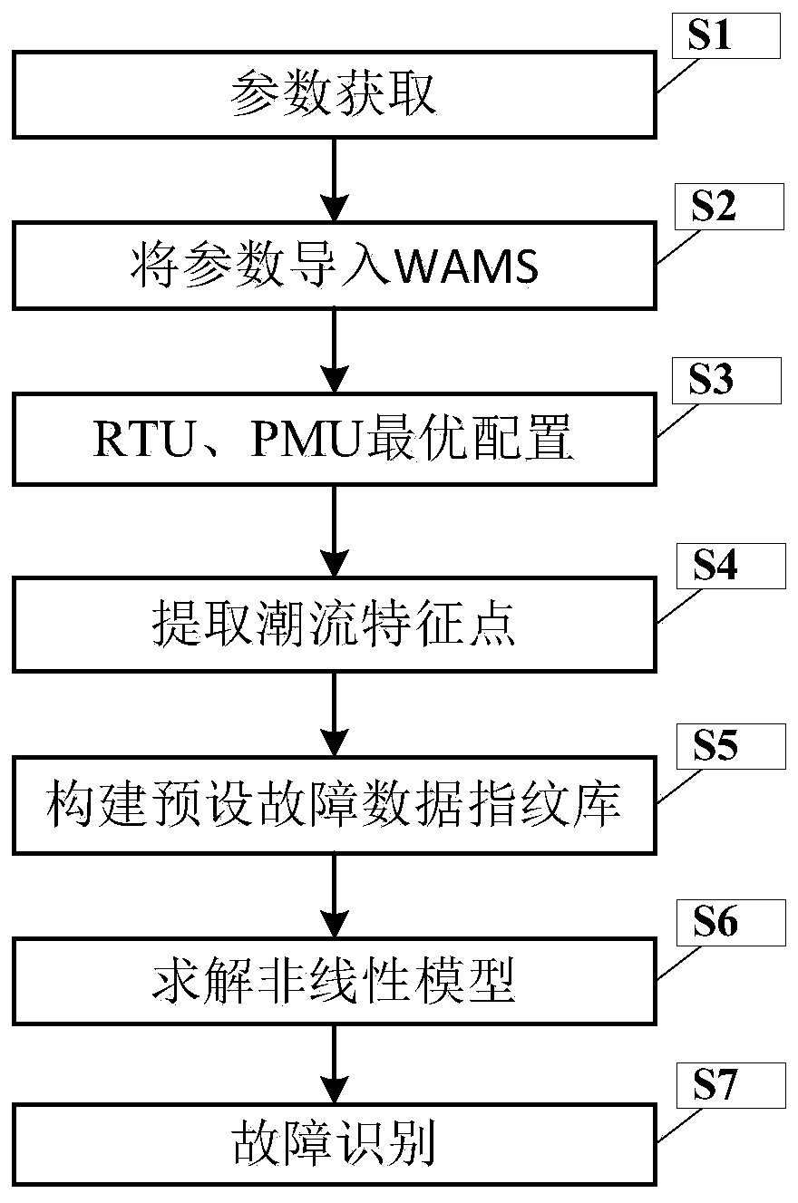
[0052] figure 1 It is a flow chart of an imprecise fault identification method for reconstruction of power grid integrity status information in the present invention.
[0053] In this example, if figure 1 As shown, the present invention is an imprecise fault identification method for reconstruction of power grid integrity state information, comprising the following steps:
[0054] S1. Obtain the operating parameters and topology parameters of the power grid, as well as the fault eigenvector of the power grid in a fault mode;
[0055] S2....
example
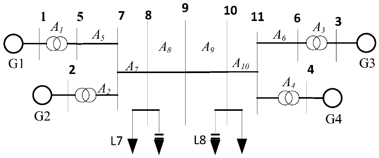
[0098] Taking the IEEE11 system as an example, use PSASP for simulation.
[0099] Add a two-phase short-circuit ground fault to each line in the system separately, and test at 10 positions of 0%, 10%, 20%, ..., 90%, 100% of the line, and divide them into 10 fault categories. mark it as A i (i=1,2,...,10). These 10 lines are sequentially numbered and marked as A 1 ~A 10 . like figure 2 As shown, when a fault occurs, the optimized configuration of the PMU collects the voltage phasor of the installation point. Assuming that the optimized RTU or PMU installation point is set to No. 3, 5, and 6 buses, the measured voltage is U 1 , U 2 , U 3 , forming the eigenvector x=[U 1 u 2 u 3 ].
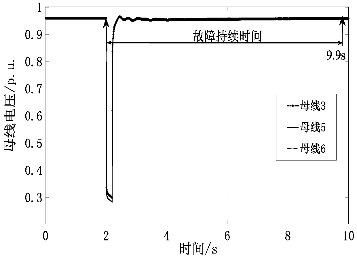
[0100] like image 3 As shown, add AB two-phase short-circuit ground fault to the midpoint of line 5-7, set the fault time to 2-2.2s, and the voltage amplitude waveform of the characteristic point (3, 5, 6) simulated by the system,
[0101] Suppose U i , i=1, 2,..., n obeys Gaussian di...
PUM
 Abstract
Description
Claims
Application Information
 - R&D
- Intellectual Property
- Life Sciences
- Materials
- Tech Scout
- Unparalleled Data Quality
- Higher Quality Content
- 60% Fewer Hallucinations
Browse by: Latest US Patents, China's latest patents, Technical Efficacy Thesaurus, Application Domain, Technology Topic, Popular Technical Reports.
© 2025 PatSnap. All rights reserved.Legal|Privacy policy|Modern Slavery Act Transparency Statement|Sitemap|About US| Contact US: help@patsnap.com


