Eureka AIR delivers breakthrough ideas for toughest innovation challenges, trusted by R&D personnel around the world.

Internal fuse protective dry self-healing high-voltage capacitor element

A technology of high-voltage capacitors and internal fuses, which is used in winding capacitors, fixed capacitor electrodes, and components of fixed capacitors, etc., can solve the problems of insufficient arcing distance, reduced reliability, and increased contacts, reducing the number of series connections, The effect of improving reliability and improving inrush current capability

Inactive Publication Date: 2003-03-19
锦州电力电容器有限责任公司
View PDF1 Cites 0 Cited by
  • Summary
  • Abstract
  • Description
  • Claims
  • Application Information

AI Technical Summary

Problems solved by technology

[0002] The coating of existing self-healing capacitor elements is an aluminum film or a zinc-aluminum film. When such elements are made into capacitors, they are oil-immersed or semi-dry (wax-soaked) structures, and their existing problems are flammable; Capacitors must be placed in a fully sealed container, and pressure protection devices are often used. When the voltage is high, the arcing distance is not enough, and arcing may occur
After its foreign invasion, the number of contacts is greatly increased, which reduces the reliability
In addition, when the fuse is blown, it will be broken from the weak point of the fuse first, and when the voltage is too high, there will be a re-ignition phenomenon

Method used


Image

  • Internal fuse protective dry self-healing high-voltage capacitor element
  • Internal fuse protective dry self-healing high-voltage capacitor element
  • Internal fuse protective dry self-healing high-voltage capacitor element

Examples


Embodiment 1

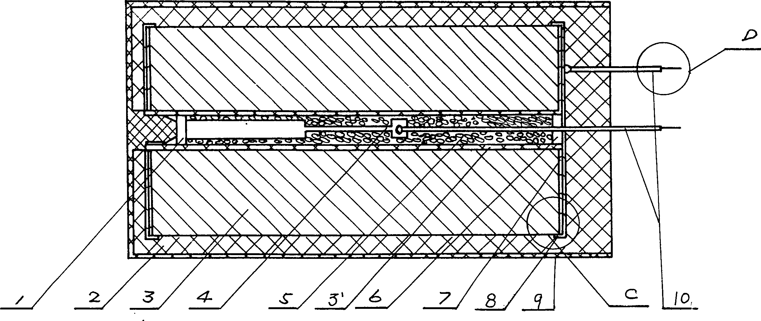
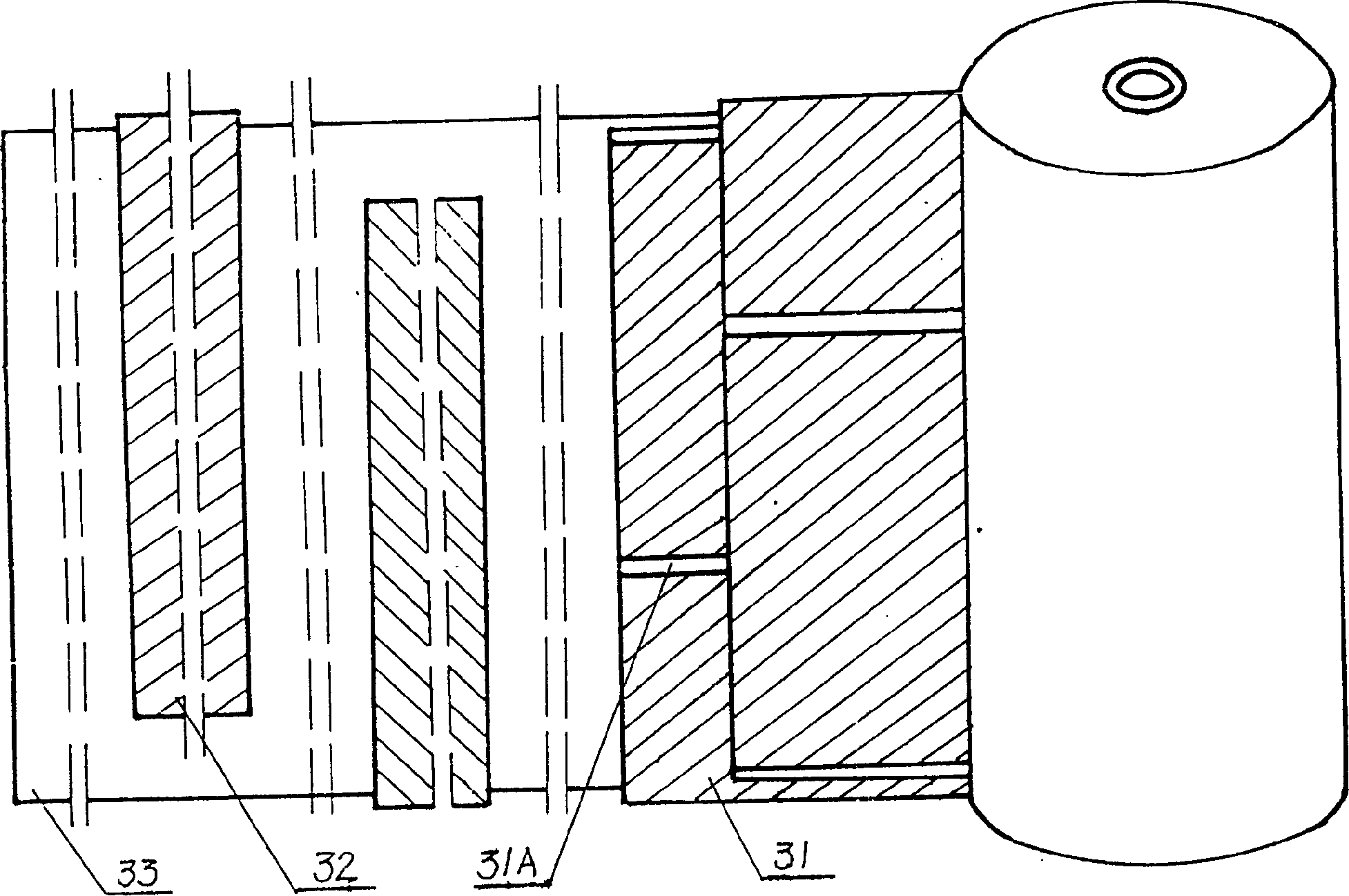
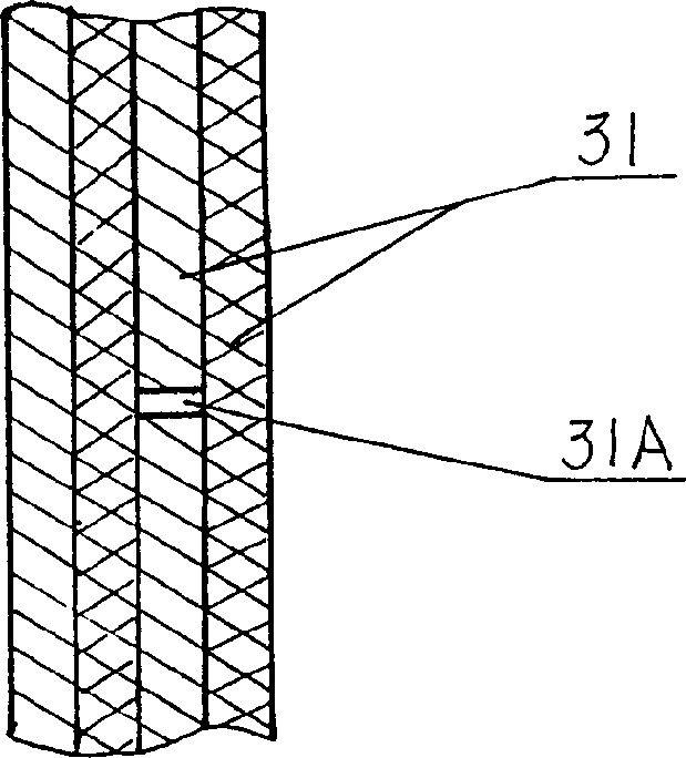
[0019] Such as figure 1 , 3 As shown in, 4, and 5, it has a frame 3, and there is a rolling element 3 on the frame 3'. The rolling element 3 includes a metalized film 31, an aluminum foil 32 and a polypropylene film 33, which respectively constitute the main capacitor And aluminum foil capacitors, in which there is an electrical isolation strip 31A on the plating layer of the metallized film 31, which makes the plating layer a two-stage electrode plate, and the adjacent plating layer forms two sets of electrode plates in series, thus forming two internal series Capacitor, an internal fuse 4 is placed in the frame 3'and filled with quartz sand 5. The two ends of the frame 3'are sealed with rubber pads 1, 6 and the internal fuse 4 is connected in series to an electrode of the component On the upper and lower end faces of the rolling element 3, there are gold spray layers 7 to connect the main capacitor and the aluminum foil capacitor in parallel, and lead out the electrode 10, and ...

Embodiment 2

[0021] Such as figure 1 , 2 As shown in, 4, and 5, it has a skeleton 3', on which there is a rolling element 3, said rolling element 3 includes a metalized film 31, an aluminum foil 32 and a polypropylene film 33, which respectively constitute the main capacitor And aluminum foil capacitors, where the plating on the adjacent metallized film 31 has a staggered electrical isolation strip 31A, so that the plating is a two-stage electrode plate, so that the plating on the adjacent metalized film 31 forms three sets of poles in series The inner fuse 4 is placed in the framework 3'and filled with quartz sand 5, and the two ends of the framework 3'are sealed with rubber pads 1, 6 to form three internal series capacitors. The wire 4 is connected in series to an electrode of the element. There are sprayed gold layers 7 on the upper and lower end faces of the rolled element 3, so that the main capacitor and the aluminum foil capacitor are connected in parallel, and the electrode lead 10 is...


PUM


Abstract

A dry-type self-healing high-voltage capacitor element includes a reel cell comprising of metallized capacitor and aluminium-foil capacitor, a sprayed golden layer and electrode wire connected in series with inner-fuse put in the element and is put in a casing filled with resin between them. The metallized capacitor has the metal film multiple-series stracture, and the said inner-fuse is surrounded with the quartz sand. The element features that low wastage, long service life and while voltage breakdown it can reliably extinguish arc and fast run down.

Description

Technical field [0001] The invention is a capacitor element used in a power system, and particularly relates to a dry self-healing high-voltage capacitor element protected by an internal fuse. Background technique [0002] The coating of the existing self-healing capacitor components is aluminum film or zinc-aluminum film. When such components are made into capacitors, they have an oil-immersed or semi-dry (wax-immersed) structure. The problem is that they are easy to burn; The capacitor must be placed in a fully sealed container, and pressure protection devices are often used. When the voltage is higher, the arcing distance is not enough, and arcing may occur. Therefore, the above-mentioned capacitors are not suitable for use in occasions with high safety requirements. A dry type self-healing capacitor component appears in China, which sets a heat shrinkable tube on the capacitor component to remove the air in the component. Because it cannot exhaust the air, the coating is easi...

Claims


Application Information

Patent Timeline
Patent Type & Authority Patents(China)
IPC IPC(8): H01G4/002H01G4/015H01G4/32
Inventor 王毅常淑云刘雪厚吴波罗少鹏侯成革
Owner 锦州电力电容器有限责任公司
Why Eureka
Eureka Blog
Learn More