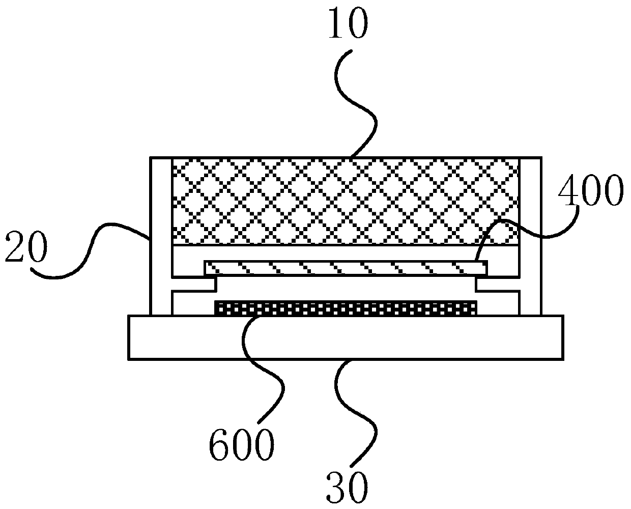
Camera module

A technology of camera module and lens module, which is applied in the direction of image communication, TV, color TV parts, etc., can solve the problems of inability to obtain resolution and poor imaging effect, achieve excellent image quality and facilitate miniaturization

Pending Publication Date: 2019-10-18
CONVERGENCE TECH CO LTD
View PDF0 Cites 5 Cited by
  • Summary
  • Abstract
  • Description
  • Claims
  • Application Information

AI Technical Summary

Problems solved by technology

Since the general photographic lens is aimed at long-distance imaging, the imaging effect is not good in the case of macro, even if the distance is increased, the magnification can only be increased but not enough resolution can be obtained.

Method used


Image

  • Camera module
  • Camera module
  • Camera module

Examples


no. 1 example

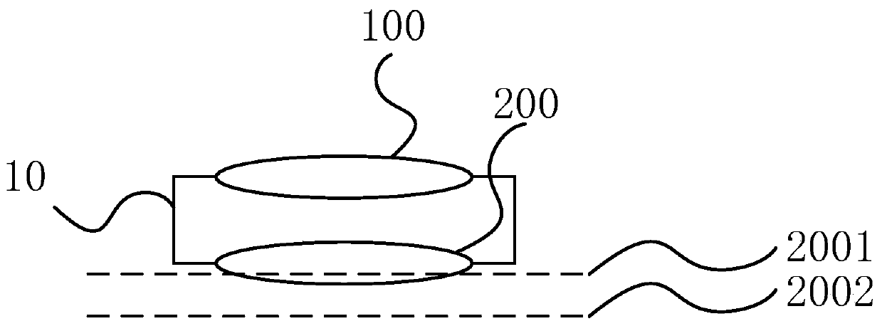
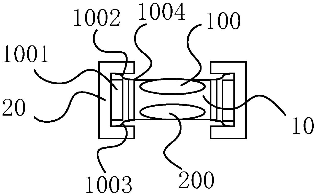
[0193] The first embodiment of the present invention Image 6 Shown. The first lens group 100 includes 4 lenses, and the second lens group 200 includes 5 lenses. The above 9 lenses are all aspherical lenses. The surface shape of the aspheric lens is represented by the curve equation as follows (the aspheric surface is formed by the curve revolving around the optical axis):

[0194]

[0195] among them:

[0196] X: The point on the aspheric surface that is Y from the optical axis, and its relative distance from the tangent to the focal point on the aspheric surface;

[0197] Y: the vertical distance between the point on the aspherical curve and the optical axis;

[0198] r: radius of curvature;

[0199] k: conic coefficient;

[0200] A i : Aspheric coefficient of order i.

[0201] The parameters of each surface of the lens in this embodiment are as Picture 12 with Figure 13 Shown.

[0202] Picture 12 The units of the length-type physical quantities such as the radius of curvature r an...

no. 2 example

[0207] The second embodiment of the present invention Figure 7 Shown. The first lens group 100 includes 4 lenses, and the second lens group 200 includes 4 lenses. The parameters of each surface of the lens in this embodiment are as Figure 14 with Figure 15 As shown, the variable definition is similar to the foregoing, and will not be repeated.

[0208] The object surface of the first lens of the first lens group 100 of this embodiment is an aspheric surface, and the curved surface is a concave surface near the optical axis, and there is an inflection point after the curved surface is a distance away from the optical axis, and the image side surface is non-spherical. The spherical surface is concave; the object surface of the second lens is aspherical, and it is convex near the optical axis, and the image surface is concave. The second lens appears to be thicker in the center than the periphery; the object of the third lens The square surface is also concave, but the degree of...

no. 3 example

[0212] The third embodiment of the present invention Figure 8 As shown, the first lens group 100 includes 3 lenses, and the second lens group 200 includes 4 lenses. The parameters of each surface of the lens in this embodiment are as Figure 16 with Figure 17 As shown, the variable definition is similar to the foregoing, and will not be repeated.

[0213] The object surface of the first lens of the first lens group 100 of this embodiment is an aspheric surface, and the curved surface is a concave surface near the optical axis, and there is an inflection point after the curved surface is a distance away from the optical axis, and the image side surface is non-spherical. The convex surface of the spherical surface; the object surface of the second lens is an aspheric convex surface, and the image surface is an aspheric concave surface; the object surface and image surface of the third lens are both aspheric convex surfaces.

[0214] The object side and image side surfaces of the fi...


PUM


Abstract

The invention discloses a camera module. The camera module comprises a lens module, a shell, a bottom plate and a photosensitive chip, the mean square error radius of the focusing image point when thedistance from the object point on the optical axis to the object space main surface of the lens module is smaller than 40mm is smaller than the mean square error radius of the focusing image point when the object point on the optical axis is located at infinity; the lens module sequentially comprises a first lens group, an aperture and a second lens group from the object side to the image side ofan optical axis, the first lens group and the second lens group have positive focal power. The object-side clear aperture of the first lens group is larger than the image-side clear aperture of the first lens group, and the object-side clear aperture of the second lens group is smaller than the image-side clear aperture of the second lens group, and specific process parameters of the position relationship between the lens module and the photosensitive surface of the photosensitive chip are given. The structure is beneficial to reducing the distance from the image side end surface of the lensto the photosensitive chip during close-range imaging, avoids adopting a distance increasing mode to realize close-range photographing, and is beneficial to miniaturization of the structure.

Description

Technical field [0001] The invention belongs to the field of imaging, and specifically relates to a camera module, in particular to a camera module for macro or microscopic imaging. Background technique [0002] Imaging devices are becoming more and more popular in life, and imaging devices such as mobile phone cameras, computer cameras, driving recorders, and surveillance cameras appear in people's daily lives every day. Imaging is becoming more and more in the direction of miniaturization, and while miniaturization can still maintain high imaging quality. In addition to the demand for taking pictures of portraits and landscapes, people also need to take pictures of close objects. Taking mobile phones as an example, models with macro camera functions have appeared in recent years. [0003] The existing macro cameras mostly use the method of increasing the image distance of the camera lens to achieve macro. Since the general camera lens is aimed at long-distance imaging, the ima...

Claims


Application Information

Patent Timeline
Patent Type & Authority Applications(China)
IPC IPC(8): H04N5/225
CPCH04N23/51H04N23/54H04N23/55
Inventor 曾绍群胡庆磊李宁李梦婷黄凯
Owner CONVERGENCE TECH CO LTD
Why Eureka
Try Eureka