Adjustable traction frame convenient for general surgery department to use

An adjustable, general surgery technology, used in medical science, fractures, etc., can solve the problems of single function, inability to adjust the traction angle, inconvenient operation, etc., and achieve the effect of simple operation.

Inactive Publication Date: 2019-10-22
宋艳玲
View PDF0 Cites 12 Cited by
  • Summary
  • Abstract
  • Description
  • Claims
  • Application Information

AI Technical Summary

Problems solved by technology

[0003] At present, the traction frame used in general surgery has a single function, can only perform traction, and cannot adjust the traction angle, and is inconvenient to operate.

Method used


Image

  • Adjustable traction frame convenient for general surgery department to use
  • Adjustable traction frame convenient for general surgery department to use
  • Adjustable traction frame convenient for general surgery department to use

Examples


Embodiment 1

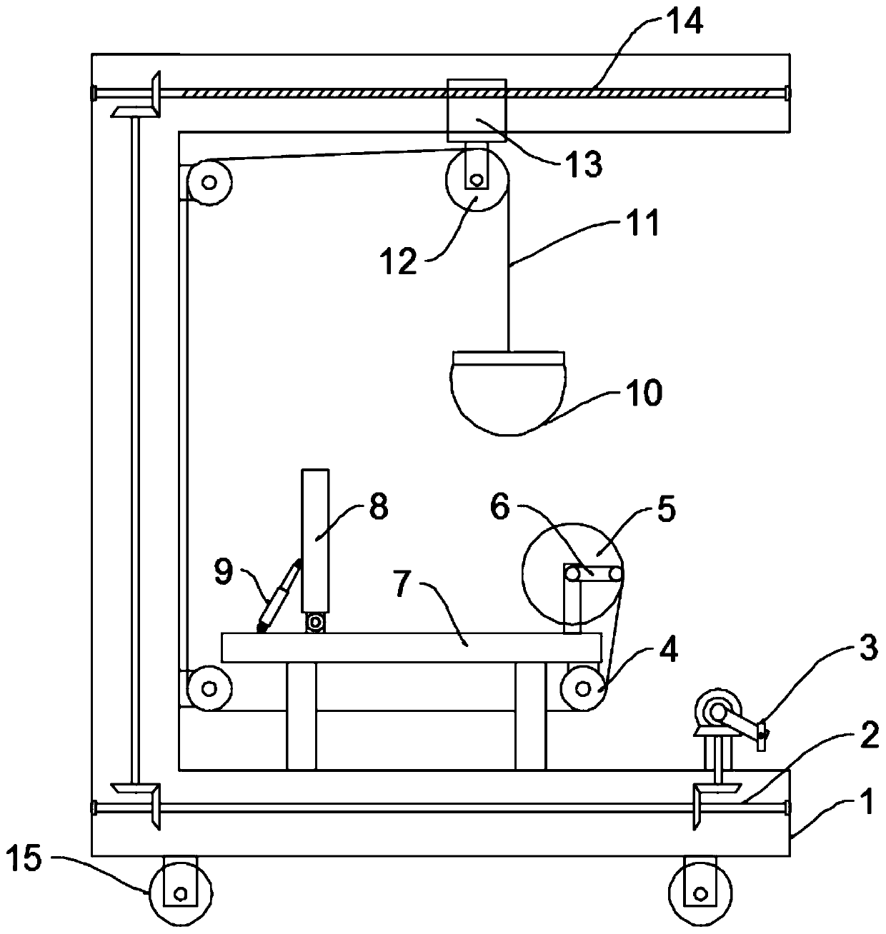
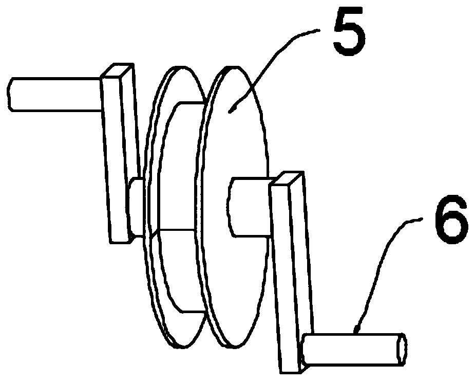
[0023] see Figure 1~2 , in an embodiment of the present invention, a convenient adjustable traction frame for general surgery, including a frame 1 and a traction unit, uniform and symmetrical rollers 15 are installed on the bottom of the frame 1, and the rollers 15 are self-locking rollers , to facilitate the movement of the device, a seat 7 is installed on the upper surface of the bottom of the frame 1, a backrest 8 is installed on the seat 7, the backrest 8 is preferably hinged with the seat 7, and a manual telescopic rod is hinged on the back of the backrest 8 9. The other end of the manual telescopic rod 9 is hinged with the seat 7. The inclination angle of the backrest 8 can be adjusted through the manual telescopic rod 9 to meet the needs of different people. The traction unit includes a traction member 10, a first traction rope 11, a The unwinding assembly for winding the first traction rope 11, the moving pulley 12 and the adjustment assembly for adjusting the positio...

Embodiment 2

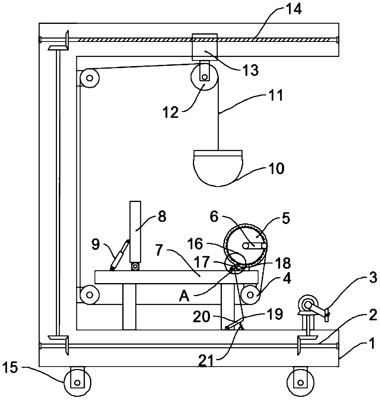
[0025] see Figure 3-4 The difference between the embodiment of the present invention and embodiment 1 is that, further, after adjusting to the most comfortable traction state, it is not necessary to hold the hand crank 6 with hands all the time, so as to liberate people's hands, and a positioning mechanism is also included. The positioning mechanism includes a ratchet 16, a pawl 17, a first compression spring 18, a second traction rope 19, a pedal 20 and a second compression spring 21. On the side, below the ratchet wheel 16, a ratchet 17 is hinged on the seat surface of the seat 7, and the ratchet 17 is engaged with the ratchet wheel 16. A first compression spring 18 is connected between the middle part of the ratchet 17 and the seat 7, and the first compression The compression spring of spring 18 makes ratchet 17 against ratchet 16 and meshes with ratchet 16 all the time, is connected with second traction rope 19 on described ratchet 17, and described pedal 20 is hingedly i...


PUM


Abstract

The invention discloses an adjustable traction frame convenient for a general surgery department to use. The adjustable traction frame comprises a rack and a traction unit. A seat is installed at theupper surface of the bottom of the rack. The traction unit comprises a traction piece, a first traction rope, a take-up and pay-off assembly for taking up and paying off the first traction rope, a movable pulley and an adjusting assembly for adjusting the position of the movable pulley. The take-up and pay-off assembly comprises a winding wheel and a crank handle. The adjusting assembly comprisesa pedal crank structure, a bevel gear transmission structure, a lead screw and a movable block. By arranging the traction unit, after the traction piece is connected with the human body, the winding wheel is rotated by the crank handle, traction is facilitated, feet drive the pedal crank structure, the pedal crank structure drives the lead screw through the bevel gear transmission mechanism to rotate, the lead screw drives the movable pulley through the movable block to move horizontally, and therefore the traction angle of the traction rope is adjusted. Furthermore, one person can rapidly adjust through synchronous cooperation of the hands and the feet to reach the most comfortable traction state, and the traction frame is easy to operate, convenient to use and practical.

Description

technical field [0001] The invention relates to the technical field of general surgery equipment, in particular to a convenient adjustable traction frame for general surgery. Background technique [0002] Cervical traction is the main method for the treatment of cervical spondylosis in general surgery. Because effective traction can relieve the compression of nerves, blood vessels, and spinal cord, and quickly relieve the symptoms of cervical spondylosis. Cervical traction is mainly to relieve neck muscle spasm, relieve pain symptoms, increase intervertebral space and intervertebral foramen, facilitate the restoration of protruding nucleus pulposus and annulus fibrosus, relieve and relieve nerve root compression and stimulation, and promote nerve root edema Absorb, relieve the compression on the vertebral artery, promote blood circulation, help local congestion, swelling and hyperplasia subside, loosen the joint capsule, improve and restore the uncinate vertebral joint, adj...

Claims


Application Information

Patent Timeline
Patent Type & Authority Applications(China)
IPC IPC(8): A61F5/042
CPCA61F5/042
Inventor 不公告发明人
Owner 宋艳玲
Why Eureka
Try Eureka