
A servo tool changer

A technology of tool changing device and tool changing mechanism, which is applied in positioning devices, manufacturing tools, tool holders, etc., and can solve the problems of many parts, heavy hydraulic pump workload, and accelerated loss of internal parts, etc.

Active Publication Date: 2021-07-06
广东圣特斯数控设备有限公司
View PDF7 Cites 0 Cited by
  • Summary
  • Abstract
  • Description
  • Claims
  • Application Information

AI Technical Summary

Problems solved by technology

[0002] Chinese patent document CN202742114U discloses a turret gear meshing structure, in which the fixed toothed disc is fixed on the outer side of the turret body, and the double toothed disc moves outward during processing to mesh with the fixed and movable toothed discs at the same time , so the fixed chainring needs to bear the outward force of the double toothed disk for a long time during work, but in the actual structure, the fixed toothed disk is locked on the turret body by screws, and the outward force borne by the fixed toothed disk finally acts on the On the above-mentioned screws, the screws will loosen after long-term use, which will cause the fixed chainring to shift easily, which will affect the normal operation of the turret; When the tool needs to be changed, it is necessary to inject hydraulic oil with a pressure of about 50 kg to overcome the elastic force of the spring and drive the double toothed plate to move. Due to the high pressure required by the hydraulic oil, the hydraulic pump has a large working load and high strength. The work will cause serious heat, accelerate the loss of internal parts, and shorten the service life of the hydraulic pump
[0003] In addition, the Chinese patent document CN202741768U discloses a turret cooling water pipeline structure. The pipeline structure is relatively complicated and involves many parts, resulting in troublesome assembly, easy damage, and easy leakage; the cooling water valve is arranged in an annular In the water tray, when the cooling water valve needs to be replaced or maintained, at least the cutter head, water seal ring and other parts need to be disassembled, which makes the disassembly operation very troublesome
It can be seen that the turret cooling water pipeline structure of this structure has problems such as easy damage, poor sealing, and troublesome maintenance in practical applications

Method used


Image

  • A servo tool changer
  • A servo tool changer
  • A servo tool changer

Examples


Embodiment Construction

[0037] The present invention will be further described below in conjunction with the accompanying drawings and embodiments.

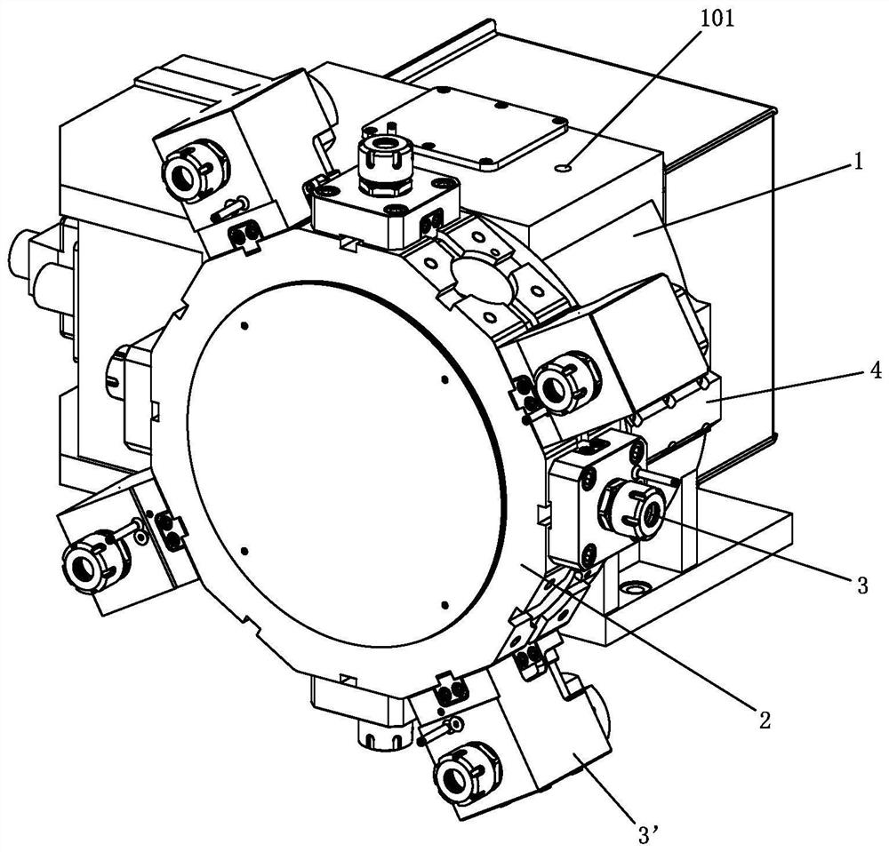
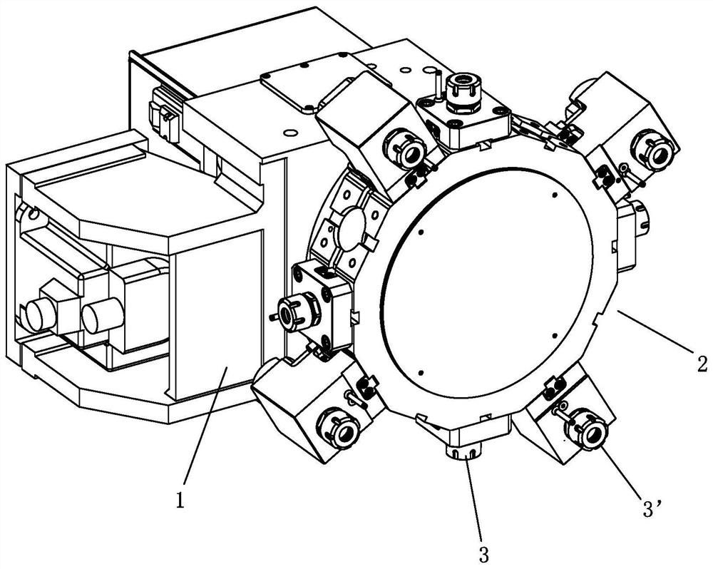
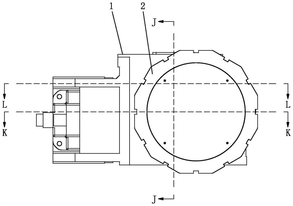
[0038] see Figure 1-Figure 15 , the servo tool changer, including

[0039] The tool change mechanism, the tool change mechanism includes a fixed box 1, and a power tool holder 2 for radially and detachably installing more than one set of tool holders. The powered tool holder 2 is rotatably arranged on the fixed box 1; the fixed box The inner side of 1 is fixed with a fixed toothed disc 4; the end surface of the power tool holder 2 is provided with a rotating toothed disc 5, which can drive the powered tool holder 2 to rotate relative to the fixed box 1 by rotating the toothed disc 5, so as to achieve the tool change effect; The knife mechanism also includes a linkage toothed disc 6 that is movable relative to the fixed box body 1 and the driven tool holder 2, and the linked toothed disc 6 moves axially relative to the fixed box body 1 and the driven t...


PUM


Abstract

The invention relates to a servo tool changing device, which includes a tool changing mechanism. The tool changing mechanism includes a fixed box body, a power tool seat and a linkage tooth plate; the fixed box body is provided with a fixed tooth plate; the power tool seat is provided with a rotating tooth plate ;During processing, the linkage gear moves towards the fixed box until it engages with the fixed gear and the rotating gear at the same time; when changing the tool, the linkage gear moves in the opposite direction until it is separated from the fixed gear and / or the rotating gear; The conduction mechanism, the coolant conduction mechanism includes a conduction fixture and a conduction movable part; the conduction fixture is provided with a first conduction channel and a conduction chamber, and the first conduction channel communicates with the liquid conduction channel on the fixed box; the conduction movable part is elastically movable In the conduction chamber, a second conduction channel is provided on the conduction movable part, and the second conduction channel communicates with the first conduction channel, and the conduction movable part elastically abuts against the driven tool seat. The invention has the advantages of reasonable force on the rotating toothed disk, reliable clutch performance, long service life, good sealing performance, and convenient disassembly and assembly of the transmission mechanism.

Description

technical field [0001] The invention relates to an automatic processing equipment, in particular to a servo tool changing device. Background technique [0002] Chinese patent document CN202742114U discloses a turret gear meshing structure, in which the fixed toothed disc is fixed on the outer side of the turret body, and the double toothed disc moves outward during processing to mesh with the fixed and movable toothed discs at the same time , so the fixed chainring needs to bear the outward force of the double toothed disk for a long time during work, but in the actual structure, the fixed toothed disk is locked on the turret body by screws, and the outward force borne by the fixed toothed disk finally acts on the On the above-mentioned screws, the screws will loosen after long-term use, which will cause the fixed chainring to shift easily, which will affect the normal operation of the turret; When the tool needs to be changed, it is necessary to inject hydraulic oil with a...

Claims


Application Information

Patent Timeline
Patent Type & Authority Patents(China)
IPC IPC(8): B23B29/32B23Q3/157B23Q11/10
CPCB23B29/32B23Q3/157B23Q11/10
Inventor 周沃强萧耀荣罗锦伟周沃华谢萍伍伟雄
Owner 广东圣特斯数控设备有限公司
Learn More