Valve sleeve boring fixture

A boring fixture and valve sleeve technology, applied in the field of hydraulic machinery manufacturing, can solve problems such as difficulty in ensuring the coaxiality of the valve sleeve and the drill body, affecting the machining accuracy, finished product quality, and deflection of the valve sleeve hole, so as to solve the problem of clamping Easy to deform, save clamping time, and disperse clamping force

Pending Publication Date: 2019-10-22
XIANGYANG HANGYU ELECTROMECHANICAL HYDRAULIC APPL TECH CO LTD
View PDF1 Cites 0 Cited by
  • Summary
  • Abstract
  • Description
  • Claims
  • Application Information

AI Technical Summary

Problems solved by technology

Existing hydraulic valves require various processing during the production process, such as drilling multiple rows of holes on the valve sleeve. Because these holes have small diameters and high processing accuracy; and the valve sleeve is cylindrical, it is difficult for conventional fixtures to be effective. Fixed and clamped, it is easy to affect the machining accuracy, so a special valve sleeve boring fixture is required
[0003] Chinese Patent No. CN200710171643.2 discloses a processing fixture for the through hole of the valve sleeve in the electro-hydraulic servo valve. The valve sleeve is fixed in the drill body by positioning pins and positioning screws. The centering is not accurate, and it is difficult to ensure the valve sleeve. It is coaxial with the jig body, so when the hole on the jig body is used to process the through hole on the valve sleeve, the hole position of the valve sleeve will be deflected, which will affect the processing accuracy and the quality of the finished product; secondly, the wall thickness of the valve sleeve is thin, When fixing with positioning pins and positioning screws, the force-bearing area is small, and clamping deformation is easy to occur during processing, resulting in scrapped products, which wastes processing time and increases costs

Method used


Image

  • Valve sleeve boring fixture
  • Valve sleeve boring fixture

Examples


Embodiment Construction

[0021] The technical solutions in the embodiments of the present invention will be clearly and completely described below in conjunction with the drawings in the embodiments of the present invention. Apparently, the described embodiments are only some of the embodiments of the present invention, not all of them. Based on the embodiments of the present invention, all other embodiments obtained by persons of ordinary skill in the art without creative efforts fall within the protection scope of the present invention.

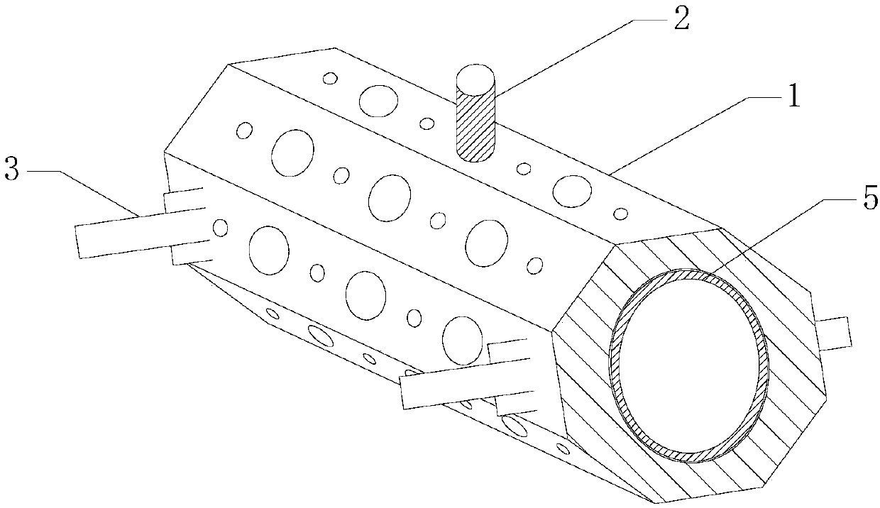
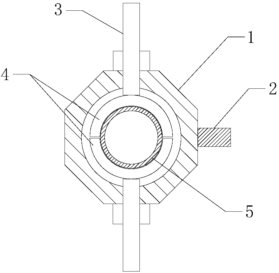
[0022] Such as Figure 1~2 As shown, a valve sleeve boring fixture includes a fixture body 1, a positioning pin 2 and a screw rod 3. The fixture body 1 is a cylindrical hollow octagonal prism, and through holes are provided on eight surfaces. The screw rod 3 passes through the clamp body 1 and is fixed on the clamp body 1 by a nut, and the screw rod 3 is arranged symmetrically on the edge of the end of the clamp body 1 . Put the valve sleeve 5 into the fixture bo...


PUM


Abstract

The invention provides a valve sleeve boring fixture and belongs to the technical field of hydraulic mechanical manufacturing. The valve sleeve boring fixture specifically comprises a fixture body, alocating pin and lead screws. The fixture body is a cylindrical hollow eight-edge prism. The eight surfaces of the fixture body are all provided with through holes. The lead screws penetrate through the fixture body and are fixed to the fixture body through nuts. The lead screws are symmetrically arranged on the edges of the fixture body. The valve sleeve boring fixture provided by the invention can enable a valve sleeve and the fixture body to be coaxial and ensure the position correctness and high precision of machining holes. Moreover, a machined valve sleeve is complete in appearance and high in rate of finished products.

Description

technical field [0001] The invention relates to the technical field of hydraulic machinery manufacturing, in particular to a valve sleeve boring fixture. Background technique [0002] Hydraulic valves are components used in hydraulic transmission to control fluid pressure, flow and direction. Existing hydraulic valves require various processing during the production process, such as drilling multiple rows of holes on the valve sleeve. Because these holes have small diameters and high processing accuracy; and the valve sleeve is cylindrical, it is difficult for conventional fixtures to be effective. Fixed clamping can easily affect the machining accuracy, so a special valve sleeve boring fixture is needed. [0003] Chinese Patent No. CN200710171643.2 discloses a processing fixture for the through hole of the valve sleeve in the electro-hydraulic servo valve. The valve sleeve is fixed in the drill body by positioning pins and positioning screws. The centering is not accurate,...

Claims


Application Information

Patent Timeline
Patent Type & Authority Applications(China)
IPC IPC(8): B23Q3/00
CPCB23Q3/00B23Q2703/10
Inventor 左彝陵
Owner XIANGYANG HANGYU ELECTROMECHANICAL HYDRAULIC APPL TECH CO LTD
Why Eureka
Try Eureka