
Electric drive fin stabilizer with speed reducer

A technology with reducer and fin stabilizer, which is applied in the direction of using hydrofoils to act on the surrounding water surface to reduce the movement of ships. It can solve the problems of limited slewing mechanism selection and the inability to guarantee equipment reliability, so as to reduce equipment quality and improve energy efficiency. Shake effect, powerful effect

Inactive Publication Date: 2019-10-22
SHANGHAI HUNTER MARINE EQUIP CO LTD
View PDF7 Cites 2 Cited by
  • Summary
  • Abstract
  • Description
  • Claims
  • Application Information

AI Technical Summary

Problems solved by technology

[0004] At present, the zero speed function has become the standard functional configuration of the anti-rolling device, but it is limited to the selection of the slewing mechanism, and the reliability of the equipment cannot be guaranteed

Method used


Image

  • Electric drive fin stabilizer with speed reducer
  • Electric drive fin stabilizer with speed reducer

Examples


Embodiment Construction

[0018] The scheme will be further described below in conjunction with the accompanying drawings and embodiments.

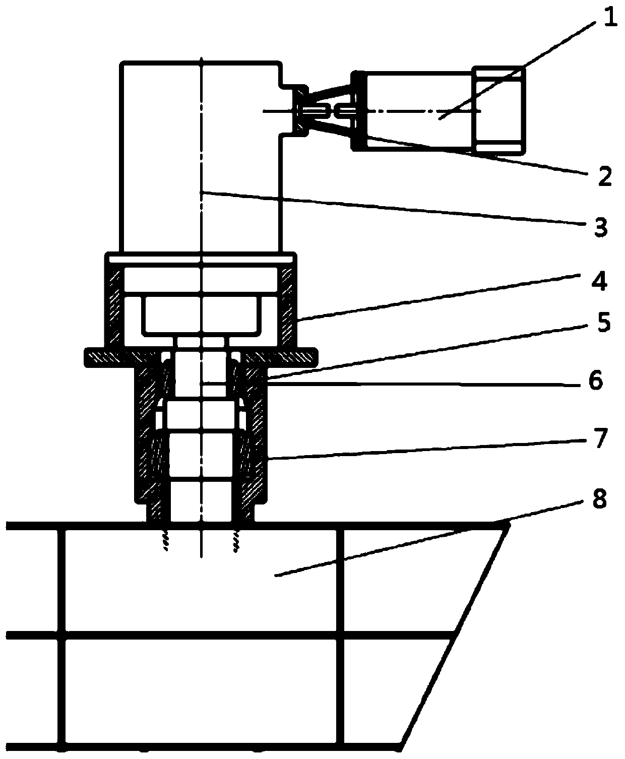
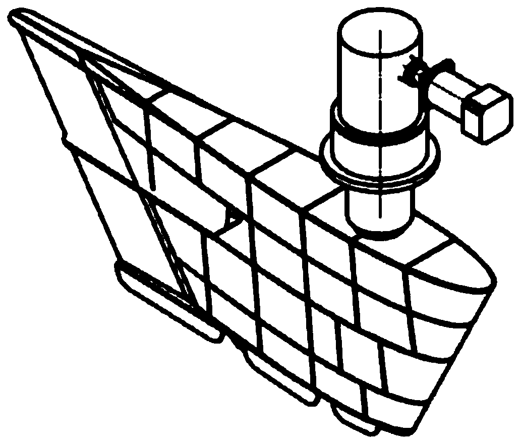
[0019] Such as figure 1 , as shown in 2, an electric drive fin stabilizer with reducer, including servo motor 1, planetary gear reducer 3, support seat 4, tapered roller bearing A5, fin shaft 6, tapered roller bearing B7, fin Leaf 8, frequency converter, driver, control box. The servo motor 1 is connected with the right-angle planetary gear reducer 3 through the mounting flange 2; the planetary gear reducer 3 is installed on the support seat 4 through the flange; the fin shaft 6 is connected with the planetary gear reducer 3 through a spline connection; the fin The shaft 6 is arranged in the support seat 4 through the tapered roller bearing A5 and the tapered roller bearing B7, and the tapered roller bearing A5 and the tapered roller bearing B7 are arranged back to back inside the support seat, and the fin blade 8 and the fin shaft 6 pass through the taper. A ti...


PUM


Abstract

The invention relates to an electric drive fin stabilizer with a speed reducer. The electric drive fin stabilizer comprises a servo motor, a planetary gear reducer, a supporting seat, a fin shaft, a fin, a frequency converter, a driver and a control cabinet, wherein the right-angle input end of the planetary gear reducer is connected to the servo motor, the output end of the planetary gear reduceris connected to the fin through the fin shaft, the planetary gear reducer is connected to the supporting seat through a flange, and the fin shaft is connected to the supporting seat through two back-to-back single-row tapered roller bearings. Compared with an existing liquid drive fin stabilizer, the electric drive fin stabilizer has the advantages that the weight is light, the structure is simple, the equipment quality can be reduced to the maximum extent, and the occupied space can be reduced; the performance is strong, the stabilization effect under various working conditions can be improved to the greatest extent, and the noise during working is greatly reduced; the maintenance is convenient; the man-machine interaction is convenient, and the energy utilization rate and stabilizationefficiency are high.

Description

technical field [0001] The invention relates to a device for reducing rolling motion of a boat, in particular to an electric drive fin stabilizer. Background technique [0002] The fin stabilizer is the most effective anti-roll device at present. It is installed in the bilge of the two sides of the ship. Form the anti-rolling moment, reduce the swing, so as to reduce the rolling of the hull. The structure of the equipment is complex, the cost is high, and the effect depends on the speed of the ship. The higher the speed, the better the effect, so it is mostly used for high-speed ships. It has two series of retractable fin stabilizer and non-retractable fin stabilizer. Ships equipped with fin stabilizers can improve the safety of the ship, improve the seaworthiness of the ship; improve the working conditions on board, improve the work efficiency of the crew; avoid cargo collision and damage; increase the speed of the ship in wind and waves, save fuel, and encourage other T...

Claims


Application Information

Patent Timeline
Patent Type & Authority Applications(China)
IPC IPC(8): B63B39/06
CPCB63B39/06
Inventor 蒋衡捷杨春云杨万富
Owner SHANGHAI HUNTER MARINE EQUIP CO LTD
Learn More