Hydraulic station for large-tonnage press machine

A technology for presses and hydraulic stations, applied in the direction of fluid pressure actuation devices, fluid pressure actuation system components, mechanical equipment, etc., can solve problems such as poor reliability, unreasonable composition, small tonnage of products, etc., and achieve stable, safe and reliable work , easy integrated control, small pressure loss effect

Inactive Publication Date: 2019-10-22
NORTHWEST A & F UNIV
View PDF0 Cites 2 Cited by
  • Summary
  • Abstract
  • Description
  • Claims
  • Application Information

AI Technical Summary

Problems solved by technology

Large-tonnage press hydraulic stations have relatively high technical requirements, because their compression resistance is particularly large, and most traditional structures cannot meet their design requirements, so large-tonnage press hydraulic stations are relatively difficult to innovate and develop slowly
After continuous innovative production in my country, although there has been great improvement and development in the field of hydraulic stations, there is still a certain gap compared with the domestic industrial development needs and foreign high-level hydraulic station technology, including the product tonnage is small, the composition Unreasonable, low performance and poor reliability, self-designed level is still in the immature stage

Method used


Image

  • Hydraulic station for large-tonnage press machine
  • Hydraulic station for large-tonnage press machine
  • Hydraulic station for large-tonnage press machine

Examples


Embodiment Construction

[0019] The present invention will be described in detail below in conjunction with the accompanying drawings.

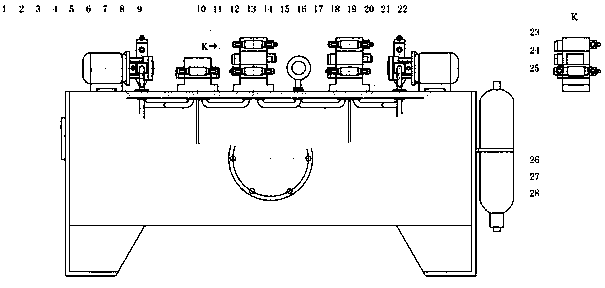
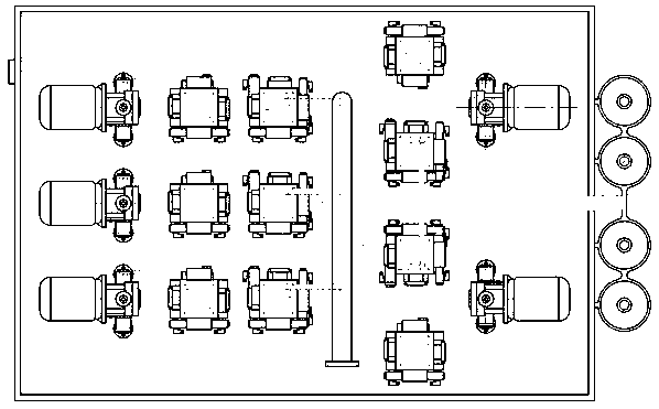
[0020] Such as figure 1 with figure 2 , a large-tonnage press hydraulic station, including a fuel tank 1, a liquid level thermometer 2, a confluence pipe 20, a filter 21, a power system, a hydraulic block group, a hydraulic valve group, an accumulator system and an oil pipe system; the power The system includes a motor 3 and a hydraulic pump 6; the hydraulic block group includes a top block 14, a middle block 15, a middle block 2 16 and a base block 19; the hydraulic valve group includes a C-type insert with a damping hole 7, Electromagnetic reversing valve 8, A-type plug-in with damping hole 9, electro-hydraulic proportional reversing valve 10, electromagnetic reversing valve 11, C-type plug-in with damping hole 2 12, electromagnetic reversing valve 2 13, electromagnetic directional valve 3 17. Pilot-operated electro-hydraulic proportional overflow valve 18, C-ty...


PUM


Abstract

The invention discloses a hydraulic station for a large-tonnage press machine. The hydraulic station comprises an oil tank, a liquid level and temperature meter, a confluence pipe, a filter, a power system, a hydraulic block set, a hydraulic valve set, an energy accumulator system and an oil pipe system, the liquid level and temperature meter is arranged on the left wall of the oil tank, the filter is arranged on the front wall of the oil tank, the energy accumulator system is arranged on the right wall of the oil tank, the power system, the hydraulic block set and the oil pipe system are distributed and arranged above the oil tank, a hydraulic pump is arranged above a motor and communicates with the oil tank and the hydraulic block set through the oil pipe system, the hydraulic valve setis arranged on the periphery of the hydraulic block set, the input end of the hydraulic block set communicates with the hydraulic pump through the oil pipe system, the output end of the hydraulic block set communicates with the confluence pipe, the energy accumulator system and the oil tank through the oil pipe system, input and output of the energy accumulator system share one end, and the energyaccumulator system communicates with the hydraulic block set and the confluence pipe through the oil pipe system. The hydraulic station has the main characteristics that the bearing capacity is large, and the hydraulic station is suitable for the press machine with the relatively large tonnage requirement; and in addition, the hydraulic station further has the advantages that the pressure loss ismall, integrated control is facilitated, the work is stable, safe and reliable and the like.

Description

technical field [0001] The invention relates to a hydraulic station providing stable pressure for a large-tonnage press, and the overall layout and design of its structure, which belongs to the technical field of hydraulic stations. Background technique [0002] Presses are extremely widely developed and used in modern society because of their functional diversity and work reliability. Small presses are mostly designed with a link mechanism, which is simple and convenient, but has a low load-carrying capacity. Large and medium-sized presses mostly use hydraulic transmission. This system has a large bearing capacity and a wide range of applications. The hydraulic station is an important foundation for large-scale pressure equipment, and it is also an important guarantee for the reliability of large-scale engineering projects and equipment. In recent years, my country's hydraulic stations have a certain self-production capacity and a corresponding scientific system. The deve...

Claims


Application Information

Patent Timeline
Patent Type & Authority Applications(China)
IPC IPC(8): F15B1/04F15B21/0423F15B13/02
CPCF15B1/04F15B13/023F15B21/041F15B21/042
Inventor 胡耀华梁宁倪福鹏
Owner NORTHWEST A & F UNIV
Why Eureka
Try Eureka