
LDMOS (Laterally Diffused Metal Oxide Semiconductor) device and formation method thereof

A device and patterning technology, applied in the direction of semiconductor devices, semiconductor/solid-state device manufacturing, electrical components, etc., can solve the problem of increased on-resistance of LDMOS devices, and achieve the effect of increasing the breakdown voltage

Pending Publication Date: 2019-10-22
SHANGHAI HUAHONG GRACE SEMICON MFG CORP
View PDF3 Cites 3 Cited by
  • Summary
  • Abstract
  • Description
  • Claims
  • Application Information

AI Technical Summary

Problems solved by technology

[0003] In order to increase the breakdown voltage, the traditional LDMOS device is realized by setting a field plate and using the field plate to deplete the drift region. However, the existing scheme to increase the withstand voltage will lead to an increase in the on-resistance of the LDMOS device.

Method used


Image

  • LDMOS (Laterally Diffused Metal Oxide Semiconductor) device and formation method thereof
  • LDMOS (Laterally Diffused Metal Oxide Semiconductor) device and formation method thereof
  • LDMOS (Laterally Diffused Metal Oxide Semiconductor) device and formation method thereof

Examples


Embodiment Construction

[0045] The present invention provides an LDMOS device and its forming method, which will be described in detail below with reference to the accompanying drawings.

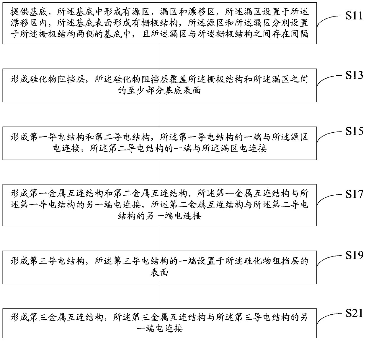
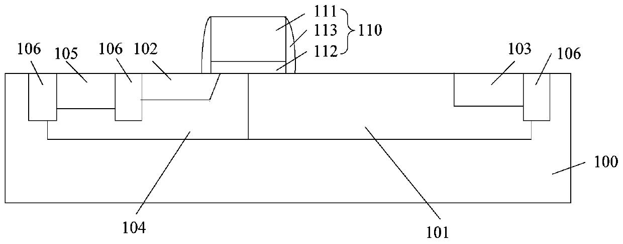
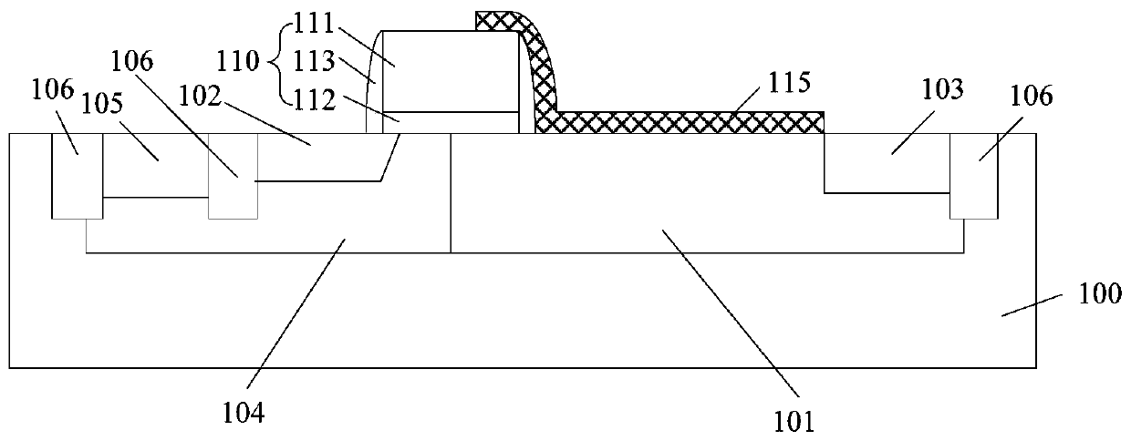
[0046] refer to figure 1 , combined with reference Figure 2 to Figure 8 , figure 1 It is a flowchart of a method for forming an LDMOS device according to an embodiment of the present invention, Figure 2 to Figure 8 It is a schematic diagram of the cross-sectional structure of an LDMOS device obtained in the relevant steps of the method for forming the LDMOS device according to an embodiment of the present invention. In some embodiments, the method for forming the LDMOS device may include the following steps.

[0047] Execute step S11, combined with reference figure 2 , providing a substrate 100 in which a drift region 101 , a source region 102 and a drain region 103 are formed, and the drain region 103 is disposed in the drift region 101 . A gate structure 110 is formed on the surface of the substrate 100, ...


PUM


Abstract

The invention provides an LDMOS (Laterally Diffused Metal Oxide Semiconductor) device and a formation method thereof. The LDMOS device comprises a substrate, a gate structure, a silicide barrier layer, a first conductive structure, a second conductive structure, a first metal interconnection structure, a second metal interconnection structure, a third conductive structure and a third metal interconnection structure, wherein substrate is provided with a source region, a drain region and a drift region, and the drain region is arranged in the drift region; the gate structure is arranged on the surface of the substrate and located between the source region and the drain region, and there is a gap between the gate structure and the drain region; the silicide barrier layer covers the surface ofat least part of the substrate between the gate structure and the drain region; one end of the first conductive structure is electrically connected with the source region; one end of the second conductive structure is electrically connected with the drain region; the first metal interconnection structure is electrically connected with the other end of the first conductive structure; the second metal interconnection structure is electrically connected with the other end of the second conductive structure; one end of the third conductive structure is arranged on the surface of the silicide barrier layer; and the third metal interconnection structure is electrically connected with the other end of the third conductive structure. The breakdown voltage of the LDMOS device is improved, the on-resistance is reduced, and the preparation process is safer and easier to control.

Description

technical field [0001] The invention relates to the technical field of semiconductor manufacturing, in particular to an LDMOS device and a forming method thereof. Background technique [0002] Laterally Diffused Metal Oxide Semiconductor (LDMOS) devices have been applied in many fields due to their performance advantages in terms of linearity, power gain, and breakdown voltage, such as mobile phones, LED displays, and LCD display drivers. High power amplifiers for wireless base stations, etc. [0003] In order to improve the breakdown voltage, the traditional LDMOS device is realized by setting a field plate and using the field plate to deplete the drift region. However, the existing solutions for increasing the withstand voltage will lead to an increase in the on-resistance of the LDMOS device. Therefore, how to take into account both the improvement of the breakdown voltage and the reduction of the on-resistance of the LDMOS device has become an urgent problem to be solve...

Claims


Application Information

Patent Timeline
Patent Type & Authority Applications(China)
IPC IPC(8): H01L29/40H01L29/06H01L29/10H01L29/423H01L29/78H01L29/66H01L21/336
CPCH01L29/402H01L29/0611H01L29/1033H01L29/4232H01L29/66689H01L29/7816H01L29/0653H01L29/42376H01L29/404H01L21/823443H01L29/16H01L29/66681
Inventor 刘宪周
Owner SHANGHAI HUAHONG GRACE SEMICON MFG CORP
Learn More