
Electro-optic Q-switched laser

A laser and electro-optical technology, applied in the field of lasers, can solve the problems of difficult crystal growth, etc., and achieve the effect of compact structure, high switching ratio and obvious effect

Pending Publication Date: 2019-10-22
福建科彤光电技术有限公司
View PDF0 Cites 1 Cited by
  • Summary
  • Abstract
  • Description
  • Claims
  • Application Information

AI Technical Summary

Problems solved by technology

However, due to its high half-wave voltage, and because the Z-cut crystal is not easy to grow into a large size, it is necessary to consider the driving power supply and crystal cost, which limits its use as an electro-optic switch in Q-switching. The application in lasers, so the active Q-switched laser market is still dominated by acousto-optic switches

Method used


Image

  • Electro-optic Q-switched laser
  • Electro-optic Q-switched laser
  • Electro-optic Q-switched laser

Examples


Embodiment 1

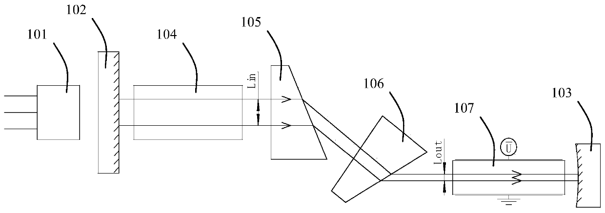
[0020] see figure 1 , this implementation case provides an electro-optic Q-switched laser, including a pumping laser system 101, the pumping laser system 101 is provided with a coaxial planar lens 102 and a gain medium 104 in turn behind the pumping focused beam, and through the gain The medium 104 sequentially compresses the lateral spot of the laser cavity mode through the first spot compression prism 105 and the second spot compression prism 106, and then passes through the BBO electro-optic crystal Q-switching switch unit 107, behind which the BBO electro-optic crystal Q-switching switch unit 107 A plano-concave output mirror 103 is provided to output Q-switched pulse laser, and the plane mirror 102 and the plano-concave output mirror 103 constitute a laser resonant cavity.

[0021] This embodiment takes Nd:YVO4 crystal as the gain medium 104 as an example to illustrate its working principle. First, the pumping laser system 101 outputs a pumping focused beam with a wavelen...

Embodiment 2

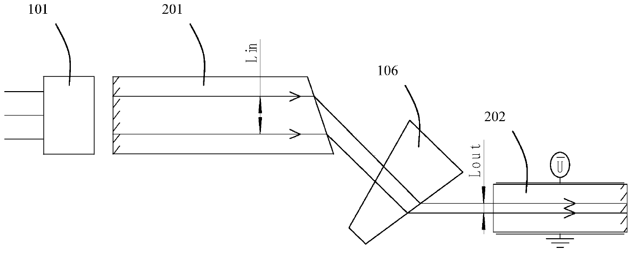
[0024] see figure 2 , the principle of obtaining electro-optic Q-switched pulsed laser and figure 1 In the same way, only the flat lens 102 and the gain medium 104 are replaced by a laser crystal 201, wherein the front surface of the laser crystal 201 is coated with HR@1064nm and AR@808nm, and the rear end surface of the laser crystal 201 is polished into a cloth angle surface to compress the light spot, BBO The rear surface of the electro-optic crystal 202 is coated with PR@1064nm. This structure is more compact and convenient for laser adjustment.

Embodiment 3

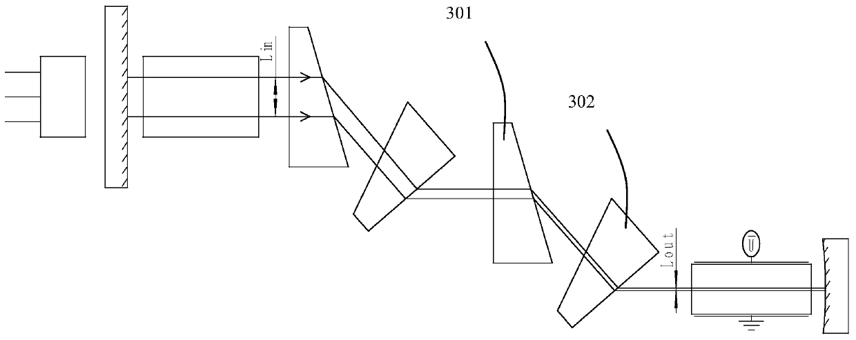
[0026] see image 3 In this embodiment, the third spot compression prism 301 and the fourth spot compression prism 302 are cascaded after the first spot compression prism 105 and the second spot compression prism 106, which can further compress the laser spot and further reduce the thickness of the electro-optic crystal electrode. In order to obtain a lower 1 / 4 wave voltage. The Q-switching principle and implementation process are the same as those in Embodiment 1, and will not be repeated here.


PUM

PropertyMeasurementUnit
Thicknessaaaaaaaaaa

Abstract

The invention discloses an electro-optic Q-switched laser, which comprises a pumping laser system. A plane lens and a gain medium are coaxially arranged behind a pumping focusing beam of the pumping laser system, and through the gain medium, a laser cavity mode lateral spot is subjected to lateral compression via a first spot compression prism and a second spot compression prism; and then, througha BBO electro-optic crystal Q-switched laser, a plano-concave output lens for outputting Q-switched pulse laser is arranged behind the BBO electro-optic crystal Q-switched laser, and the plane lens and the plano-concave output lens form a laser resonant cavity. The beam in the laser resonant cavity is subjected to lateral compression through the spot compression prisms, the lateral light passingsize of the electro-optical switch can be processed small, a thin plate structure is achieved, the half-wave voltage of the electro-optic switch can thus be reduced, and low-switching voltage high-switch ratio electro-optic Q-switched laser output can be realized.

Description

technical field [0001] The invention belongs to the technical field of lasers, in particular to an electro-optic Q-switched laser. Background technique [0002] Because of its high peak power and single pulse energy, pulsed lasers are favored in industrial processing and other fields. We know that the methods of obtaining pulsed laser output are mainly divided into active Q-switching, passive Q-switching and mode-locking. Among these methods, active Q-switching pulsed laser technology is undoubtedly the most mature and widely used at present, and also obtains the highest average It is an effective means of power pulsed laser, and the active Q-switched laser modulation parameters are artificially controllable, which is the main way to obtain a stable repetition frequency pulse train. Generally, active Q-switched lasers are divided into electro-optic and acousto-optic switch modulations, each of which has its own advantages and disadvantages. [0003] Electro-optic switch Q-...

Claims


Application Information

Patent Timeline
IPC IPC(8): H01S3/115H01S3/08
CPCH01S3/115H01S3/08
Inventor 校金涛陈基平
Owner 福建科彤光电技术有限公司
Learn More