
Preparation method of hip joint bone cement interposition and special bending machine thereof

A technology for bone cement and hip joint, applied in the medical field, can solve problems such as difficulty in walking, poor postoperative function, and difficulty in accurately controlling length and angle, and achieve the effects of convenient accuracy, good practicability, and improved surgical efficiency and effect.

Pending Publication Date: 2019-10-25
GUANGZHOU HUATAI 3D MATERIAL MFG TECH CO LTD +1
View PDF0 Cites 0 Cited by
  • Summary
  • Abstract
  • Description
  • Claims
  • Application Information

AI Technical Summary

Problems solved by technology

In the second-stage revision operation, if only the prosthesis is removed in the first operation, the hip joint will not be supported, the postoperative function will be poor, and it will be difficult to walk, and the original prosthesis will lose its space, and the soft tissue will be contracted, resulting in the second operation. The new prosthesis cannot be implanted
The disadvantages of this method are: 1. The manufacturing process is rough, it is difficult to accurately control the length and angle, and the risk of mismatch is high, which affects the efficiency and effect of the operation; 2. The cement deforms with the shape of the medullary cavity, and it is often difficult to remove the bone cement in the second-stage operation Case
[0006] Mold production: Standardized prosthesis, represented by Johnson & Johnson’s prostalac cement casting system, is a special prosthesis-shaped bracket that matches the femoral stem casting mold to cast the interposed femoral part, but the surface of the prostalac system is not completely covered with cement, but The metal femoral head and femoral neck are exposed, which is not conducive to infection control in theory

Method used


Image

  • Preparation method of hip joint bone cement interposition and special bending machine thereof
  • Preparation method of hip joint bone cement interposition and special bending machine thereof
  • Preparation method of hip joint bone cement interposition and special bending machine thereof

Examples


Embodiment 1

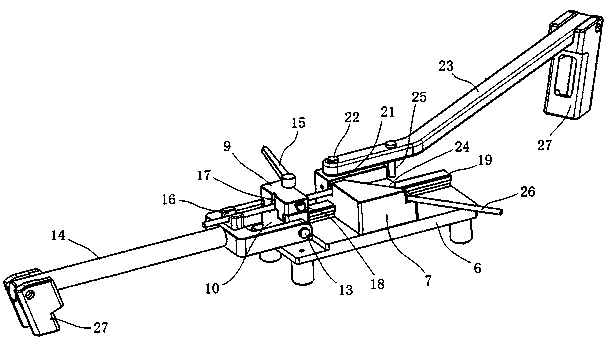
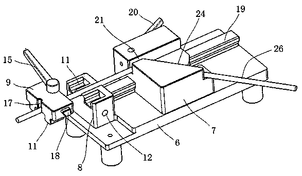
[0033] This example proposes a preparation method of a bone cement interposition of the hip joint and its special bending machine. The preparation method of the bone cement interposition of the hip joint has the advantages of high shape precision of the interposition, convenient preparation, and no metal exposure , can effectively improve the preparation efficiency and improve the operation effect. The bending machine has the advantages of convenient use and high precision.

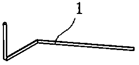
[0034]The preparation method of the hip joint bone cement interposition of the present invention is as follows: first cast the interposition femoral stem 2 with the metal bracket 1, and ensure that the tail end of the metal bracket 1 is embedded in the interior of the interposition femoral stem 2; The head end of the interposition femoral stem 2 is put into the femoral head casting mold 3, and finally the interposition femoral head 4 connected with the interposition femoral stem 2 is cast, and the interpos...


PUM


Abstract

The invention provides a preparation method of a hip joint bone cement interposition and a special bending machine thereof. The preparation method comprises the following steps that firstly, an interposition femoral stem with a metal scaffold is casted, and it is ensured that the tail end of the metal scaffold is buried in the interposition femoral stem; then the head end of the interposition femoral stem is put into a femoral head casting mould, finally, an interposition femoral head connected with the interposition femoral stem into a whole is casted, and the interposition femoral stem and the interposition femoral head jointly form the hip joint bone cement interposition. The preparation method abandons a manual fabricating mode, and by adopting a method for casting the interposition femoral stem and the interposition femoral head step by step, the shaping accuracy is ensured, and the matching degree is improved; it is avoided that the tail end of the metal scaffold is exposed fromthe interposition femoral stem when the interposition femoral stem is casted, so that after the hip joint bone cement interposition is casted, the metal scaffold cannot be exposed to the outside, thereby reducing or avoiding the infection problem of an operative site of a patient.

Description

technical field [0001] The invention belongs to the field of medical technology, and in particular relates to a preparation method of a bone cement interstitial of the hip joint and a special bending machine thereof. Background technique [0002] Hip interstices are implants used in secondary revision surgery for periprosthetic hip infections. [0003] Hip replacement is the replacement of an irreparably diseased hip with an artificial hip prosthesis. Like all surgical procedures, surgical site infection may occur after hip replacement. Periprosthetic infection of the hip joint refers to the infection deep around the hip joint prosthesis. This type of infection often requires two operations because bacteria form an antibiotic-resistant bacterial film on the surface of the prosthesis: the first operation removes the original prosthesis body, to provide conditions for infection control, and then treated with antibiotics for a period of time, after the infection is cured, a se...

Claims


Application Information

Patent Timeline
IPC IPC(8): A61F2/46B28B23/00B21F1/00
CPCA61F2/4644B28B23/00B21F1/00
Inventor 肖何王健史占军朱献文陆国赞朱纬纬
Owner GUANGZHOU HUATAI 3D MATERIAL MFG TECH CO LTD
Learn More