
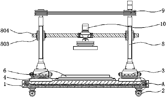
Screw cap machining equipment with lifting structure and capable of directionally moving

A technology of directional movement and lifting structure, which is applied in the direction of metal processing equipment, grinding/polishing equipment, manufacturing tools, etc., can solve the problems of insufficient automation ability, affecting the processing accuracy of nuts, difficult to process structure lifting operations, etc., to avoid The effect of horizontal fracture and stable connection

Inactive Publication Date: 2019-10-25
DONGGUAN XIANGFEI INTELLIGENT EQUIP TECH CO LTD
View PDF1 Cites 4 Cited by
  • Summary
  • Abstract
  • Description
  • Claims
  • Application Information

AI Technical Summary

Problems solved by technology

[0004] Aiming at the deficiencies of the prior art, the present invention provides a directional movable nut processing equipment with a lifting structure, which solves the problem that the internal and external structures proposed in the above-mentioned background technology are relatively simple, and the automation ability in the process of use is obviously insufficient , and it is difficult to realize the lifting operation of the processing structure, which seriously affects the processing accuracy of the nut and cannot well meet people's needs.

Method used


Image

  • Screw cap machining equipment with lifting structure and capable of directionally moving
  • Screw cap machining equipment with lifting structure and capable of directionally moving
  • Screw cap machining equipment with lifting structure and capable of directionally moving

Examples


Embodiment Construction

[0026] The following will clearly and completely describe the technical solutions in the embodiments of the present invention with reference to the accompanying drawings in the embodiments of the present invention. Obviously, the described embodiments are only some, not all, embodiments of the present invention.

[0027] In the description of the present invention, unless otherwise stated, the meaning of "plurality" is two or more; the terms "upper", "lower", "left", "right", "inner", "outer" , "front end", "rear end", "head", "tail", etc. indicate the orientation or positional relationship based on the orientation or positional relationship shown in the drawings, and are only for the convenience of describing the present invention and simplifying the description, rather than Indicates or implies that the device or element referred to must have a particular orientation, be constructed and operate in a particular orientation, and therefore should not be construed as limiting the...


PUM


Abstract

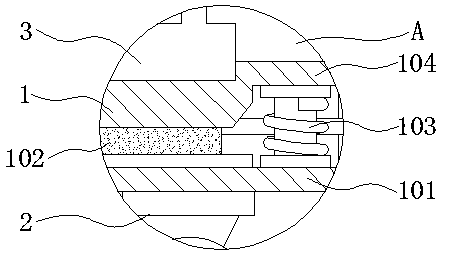
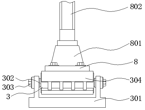
The invention discloses screw cap machining equipment with a lifting structure and capable of directionally moving, relates to the technical field of screw cap machining equipment, and in particular to the screw cap machining equipment with the lifting structure and capable of directionally moving. The screw cap machining equipment comprises a buffer base, a machining face board and lifting mechanisms, wherein universal wheels are arranged below the buffer base, and the two sides of the upper part of the buffer base are provided with directional transmission structures correspondingly; limiting rings are arranged between the directional transmission structures, fixing screws are installed inside the edges of the limiting rings; mounting holes are formed in the machining face board, and power transmission structures are arranged above the lifting mechanisms. According to the screw cap machining equipment with the lifting structure and capable of directionally moving, the using performance of the whole device is greatly improved while the structure is improved, the improved equipment can carry out effective lifting adjusting operation in the using process, the machining equipment canhave the directional moving capability, so that the use requirements of people are effectively met.

Description

technical field [0001] The invention relates to the technical field of nut processing equipment, in particular to a directional movable nut processing equipment with a lifting structure. Background technique [0002] A nut is a nut, a part that is screwed together with a bolt or a screw for fastening. A component that must be used in all manufacturing machinery is divided into several types such as carbon steel, stainless steel, and non-ferrous metals according to different materials. [0003] An easy-to-use nut processing equipment disclosed in the Chinese invention patent application publication CN207188933U, although the easy-to-use nut processing equipment can make the wire cutter move up and down stably, when the adjusting rod is pushed, it can make the wire cutter move stably. Move left and right and push the two L-shaped clamps backwards, place the nut and the screw between the two sets of L-shaped clamps respectively, and under the action of the elastic force of the ...

Claims


Application Information

Patent Timeline
IPC IPC(8): B24B19/00B24B41/06B24B47/12B24B47/22
CPCB24B19/00B24B41/06B24B47/12B24B47/22
Inventor 王龙李德源
Owner DONGGUAN XIANGFEI INTELLIGENT EQUIP TECH CO LTD
Learn More