Eureka AIR delivers breakthrough ideas for toughest innovation challenges, trusted by R&D personnel around the world.

Underground building box type air pollution prevention and treatment device

An air pollution and underground building technology, which is applied in the directions of air quality improvement, heating method, air conditioning system, etc., can solve the problems of poor air circulation, air pollution in underground buildings, air deterioration in underground buildings, etc. Good handling effect and good ventilation effect

Inactive Publication Date: 2019-10-25
WUHAN UNIV OF SCI & TECH
View PDF11 Cites 0 Cited by
  • Summary
  • Abstract
  • Description
  • Claims
  • Application Information

AI Technical Summary

Problems solved by technology

[0002] With the continuous development of science and technology, the technical level of the construction industry is getting higher and higher, and the places where underground buildings appear are becoming more and more common. The development of underground space is conducive to alleviating the problem of insufficient space on the ground, providing modern society with It is very convenient, but because the ventilation conditions of underground buildings are not as convenient as those on the ground, the air in underground buildings cannot circulate well, which leads to serious air pollution problems in underground buildings, while the existing air Most of the pollution prevention and control devices are bulky and cannot be conveniently used underground, which further leads to the deterioration of the air in underground buildings
Therefore, the existing technology cannot efficiently prevent and control the air pollution of underground buildings.

Method used


Image

  • Underground building box type air pollution prevention and treatment device
  • Underground building box type air pollution prevention and treatment device
  • Underground building box type air pollution prevention and treatment device

Examples


Embodiment Construction

[0024] The following will clearly and completely describe the technical solutions in the embodiments of the present invention with reference to the accompanying drawings in the embodiments of the present invention. Obviously, the described embodiments are only some, not all, embodiments of the present invention. Based on the embodiments of the present invention, all other embodiments obtained by persons of ordinary skill in the art without making creative efforts belong to the protection scope of the present invention.

[0025] In describing the present invention, it should be understood that the terms "center", "longitudinal", "transverse", "upper", "lower", "front", "rear", "left", "right", The orientations or positional relationships indicated by "vertical", "horizontal", "top", "bottom", "inner", "outer", etc. are based on the orientation or positional relationships shown in the drawings, and are only for the convenience of describing the present invention Creation and sim...


PUM


Abstract

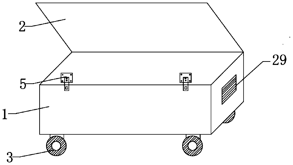
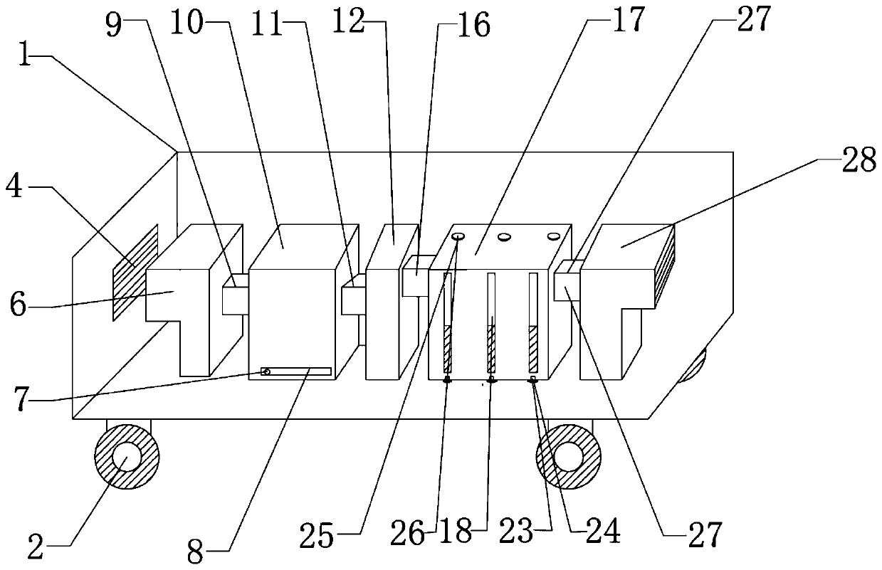
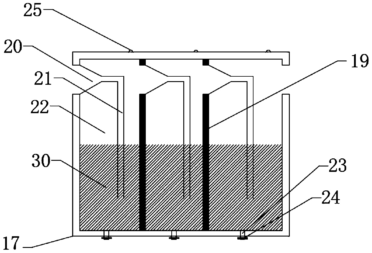
The invention discloses an underground building box type air pollution prevention and treatment device which comprises a box body and a box cover. The box body is of a cuboid cavity structure. The boxbody and one side of the box cover are hinged. The box body and the other side of the box cover are closed through a locking buckle. A first wind inlet is formed in the left side face of the box body. A first exhausting opening is formed in the right side face of the box body. An air blower, an electrostatic dust collector, an activity carbon filter, a chemical reactor and a supply fan are arranged in the box body. The chemical reactor is of a hollow cuboid structure. A second wind inlet is formed in the left side face of the chemical reactor. A second exhausting opening is formed in the right side face. Multiple baffles are arranged in the chemical reactor at intervals. Each baffle is provided with a circulating opening. The multiple baffles separate the interior of the chemical reactorinto multiple reaction chambers. Reaction liquid is contained in each reaction chamber. The underground building box type air pollution prevention and treatment device is simple in structure, convenient to use, practical, and capable of effectively preventing and treating underground building air pollution.

Description

technical field [0001] The invention relates to the field of pollution prevention and control, in particular to a box-type air pollution prevention and control device for underground buildings. Background technique [0002] With the continuous development of science and technology, the technical level of the construction industry is getting higher and higher, and the places where underground buildings appear are becoming more and more common. The development of underground space is conducive to alleviating the problem of insufficient space on the ground, providing modern society with It is very convenient, but because the ventilation conditions of underground buildings are not as convenient as those on the ground, the air in underground buildings cannot circulate well, which leads to serious air pollution problems in underground buildings, while the existing air Most of the pollution prevention and control devices are bulky and cannot be conveniently used underground, which ...

Claims


Application Information

Patent Timeline
IPC IPC(8): F24F3/16F24F13/28
CPCF24F13/28F24F8/10F24F8/158F24F8/192Y02A50/20
Inventor 陈道家江志刚王三平刘驿轩丁周阳于李鹏
Owner WUHAN UNIV OF SCI & TECH
Why Eureka
Eureka Blog
Learn More