An optical fiber wire harness crimping machine

A fiber optic wire and bundle pressing technology, which is applied in the field of crimping machines, can solve problems such as difficult control of the descending height of the punching head, unqualified crimping of optical fiber wire harnesses, and piercing of the insulation layer of optical fiber wires, so as to avoid excessive insulation crimping height or too low, ensuring reliability and reducing damage rate

Active Publication Date: 2020-12-04
LINYI HAINA ELECTRONICS
View PDF5 Cites 0 Cited by
  • Summary
  • Abstract
  • Description
  • Claims
  • Application Information

AI Technical Summary

Problems solved by technology

[0004] When the existing optical fiber wire harness crimping machine is crimping the terminal, because the descending height of the punching head is difficult to control, when the punching head descends too deep, the punching head will continue to descend after crimping the terminal, thus causing puncture or cutting to the insulation layer of the optical fiber wire. In the worst case, when the punching head descends too shallowly, the terminal cannot be effectively crimped, so that the connection between the optical fiber harness and the terminal is too loose, resulting in unqualified crimping of the optical fiber harness

Method used


Image

  • An optical fiber wire harness crimping machine
  • An optical fiber wire harness crimping machine
  • An optical fiber wire harness crimping machine

Examples


Embodiment Construction

[0033] In order to make the technical means realized by the present invention, creative features, goals and effects easy to understand, the following combination Figure 1 to Figure 8 , to further elaborate the present invention.

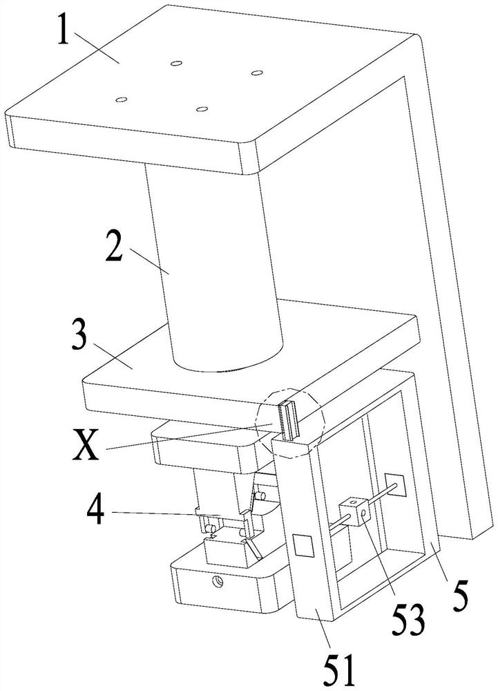
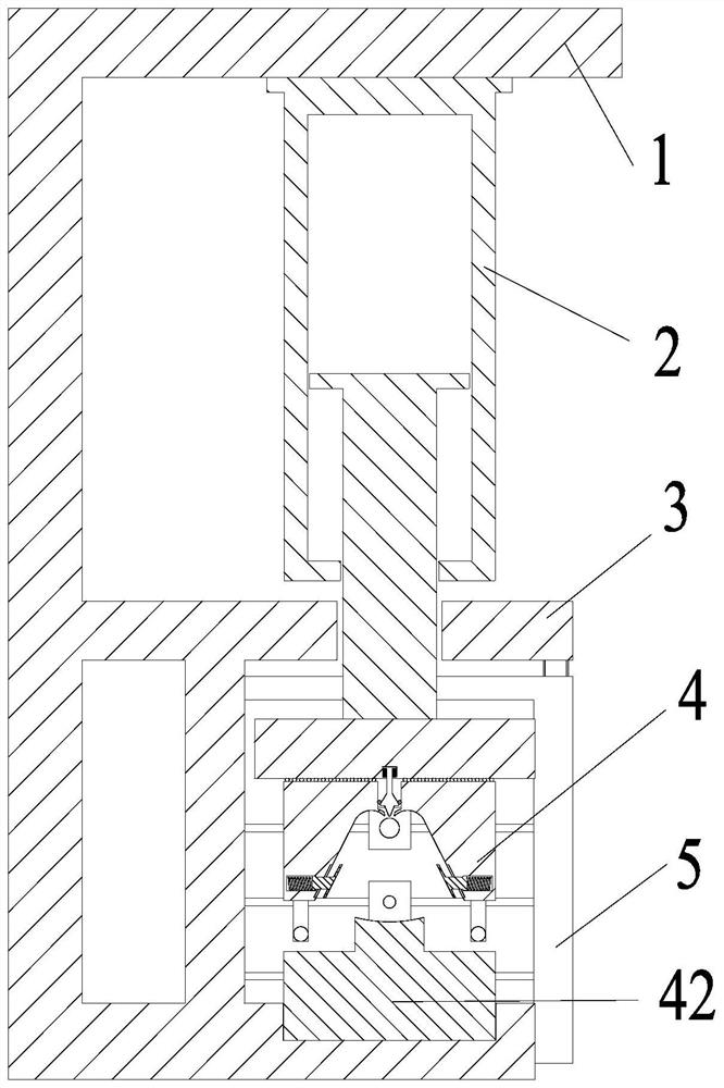
[0034] An optical fiber wire harness crimping machine, comprising an L-shaped mounting plate 1, a cylinder 2, a mounting table 3, a crimping device 4 and a rotating length fixing device 5, the upper end of the L-shaped mounting plate 1 is equipped with a cylinder 2, and the L-shaped mounting plate 1. An installation platform 3 is installed at the lower end, and a crimping device 4 is arranged inside the installation platform 3, and a rotating length-fixing device 5 is installed on the right side of the installation platform 3; wherein:

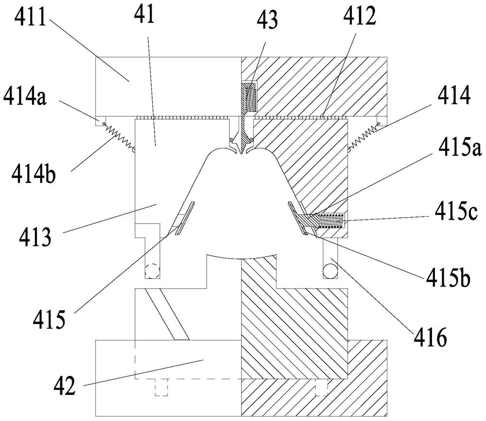
[0035] The crimping device 4 includes a sliding crimping device 41, a fixed crimping die 42 and a secondary crimping device 43. The upper end of the sliding crimping device 41 is connected to the ejection end of the...


PUM


Abstract

The invention relates to an optical fiber wire harness crimping machine which comprises an L-shaped mounting plate, a cylinder, a mounting table, a crimping device and a rotating fixed length device.An upper end of the L-shaped mounting plate is equipped with a cylinder, a lower end of the L-shaped mounting plate is equipped with the mounting table which is internally provided with the crimping device, and a right side of the mounting table is equipped with the rotating fixed length device. According to the optical fiber wire harness crimping machine, the problems that a punching head continuous to fall after crimping a terminal when the lowering of the punching head is too deep since the lowering height of the punching head is difficult to control when an existing optical fiber harness crimping machine crimps the terminal, therefore, a fiber wire insulating layer is pierced or cut, the terminal cannot be effectively crimped when the lowering of the punching head is too shallow, the connection between a fiber harness and the terminal is too loose and so the crimping of the fiber harness is unqualified are solved.

Description

technical field [0001] The invention relates to the field of crimping machines, in particular to an optical fiber wire harness crimping machine. Background technique [0002] Optical fiber crimping machine, also known as terminal crimping machine, is used to crimp terminals after stripping wires. The mechanical structure is simple, the cost is relatively low, and it has been mass-produced in the industry, and the single-head wire harness products are widely used in the industry. Terminal crimping machine refers to a machine used in wire processing, which can crimp the metal head to the wire end, and then conduct it. The terminals crimped by the terminal crimping machine are usually for more convenient connection, and the two wires can be stably connected together without soldering, and only need to be unplugged when dismantling. [0003] In actual production and manufacturing, the existing optical fiber wire harness crimping machine has the following problems in the actual...

Claims


Application Information

Patent Timeline
Patent Type & Authority Patents(China)
IPC IPC(8): G02B6/38
CPCG02B6/3898
Inventor 倪敏跃张盼盼张赛
Owner LINYI HAINA ELECTRONICS
Why Eureka
Try Eureka