Laser projection light source

A laser projection and light source technology, applied in optics, instruments, projection devices, etc., can solve the problems of high light energy density, affecting the reliability of laser projection light machine, etc., achieve uniform energy, simple and effective powder burning risk, and solve the problem of powder burning risk effect

Active Publication Date: 2019-10-25
SICHUAN CHANGHONG ELECTRIC CO LTD
View PDF10 Cites 2 Cited by
  • Summary
  • Abstract
  • Description
  • Claims
  • Application Information

AI Technical Summary

Problems solved by technology

In particular, due to the high energy density of light at the central point, there will be a r

Method used


Image

  • Laser projection light source
  • Laser projection light source
  • Laser projection light source

Examples


Embodiment 1

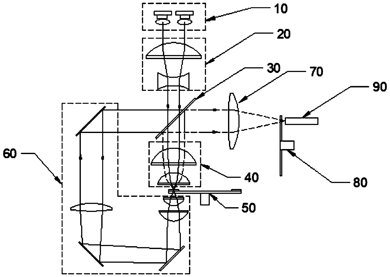
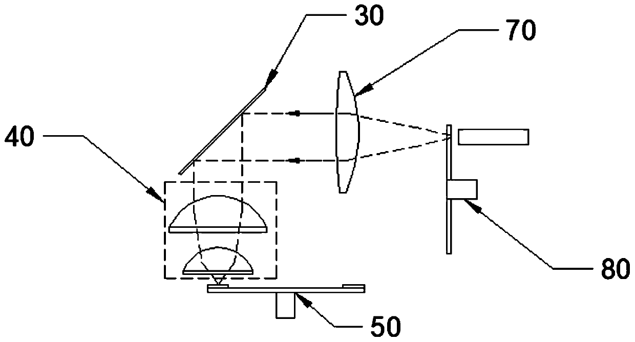
[0033] Such as figure 1 As shown, this embodiment provides a laser projection light source, including a laser array 10, a telephoto component 20, a dichroic color separation component 30, a light receiving component 40, a phosphor wheel device 50, a blue light path 60, a light concentrating component 70, Color wheel assembly 80 and light bar assembly 90. The laser beam emitted by the laser array 10 is focused on the surface of the phosphor wheel 50 after passing through the telescopic assembly 20 , the dichroic separation assembly 30 and the light collection assembly 40 .

[0034] Such as Figure 5 As shown, the fluorescent powder wheel device 50 in this embodiment includes a substrate and a motor, and the two are coaxially connected, and the motor drives the substrate to rotate at a high speed. The substrate is a reflective metal substrate, including a first fluorescent area 50a, a second The fluorescent area 50b and the first hollow area 50c.

[0035] Wherein, the first p...

Embodiment 2

[0045] This embodiment is the same as the optical path structure and basic principle of Embodiment 1, such as Figure 7 As shown, the difference is that the technical solutions of the color filter wheel device 70 are different.

[0046] Such as Figure 7 As shown, in this embodiment, the substrate of the first filter area 80a is composed of a diffuser 803 and a color filter 804, with a gap of 0-0.2 mm in between. In this embodiment, two combined substrates are used instead of one integral substrate, which increases the degree of freedom of setting the diffuse scattering surface, and technicians can flexibly set the number or position of the diffuse scattering surface according to the effect.

[0047] Among them, the first surface of the diffuser 803 is a diffuse scattering surface, HWHM=3°, and the second surface is a mirror surface; the first surface of the color filter 804 is a mirror surface, coated with an anti-reflection coating, and the second surface is a mirror surfac...


PUM

PropertyMeasurementUnit
Energy densityaaaaaaaaaa

Abstract

The invention discloses a laser projection light source, which comprises a laser array, a telescopic assembly, a dichromatic assembly, a light receiving assembly, a fluorescent powder wheel device, ablue light path, a light gathering assembly, a color wheel device and a light bar assembly, wherein a laser beam emitted by the laser array penetrates through the telescopic assembly, the dichromaticassembly and the light receiving assembly and is then focused on the surface of the fluorescent powder wheel device. The first surface of a red filter area of the color wheel device is a scattering surface, the second surface is a long-wave-pass filter film, and light in a reflected wave band penetrates through a diffuse scattering surface twice, so that the energy is more uniform when a reflectedlight spot irradiates the surface of the surface of fluorescent powder, and the energy density at the center point is reduced; and the powder burning risk of the high-brightness laser projection system can be simply and effectively solved.

Description

technical field [0001] The invention relates to the technical field of laser projection display, in particular to a laser projection light source. Background technique [0002] Laser projection display is a newly developed projection technology, which uses semiconductor lasers as light sources to replace traditional light sources; the existing technical solutions mainly use blue light lasers to excite phosphors to produce red, green, and yellow light, and then synthesize white light through a photocombining system . There are two main sources of red light, one is that blue light excites red phosphor powder to emit red light, and the other is blue light excites yellow phosphor powder to emit yellow light, and then filters out red wavelength light through the filter color wheel. Due to the low high-temperature efficiency of the red phosphor and the serious light decay problem, in the prior art, the method of exciting the yellow phosphor to emit yellow light and then filtering...

Claims


Application Information

Patent Timeline
IPC IPC(8): G03B21/20G03B21/16
CPCG03B21/16G03B21/204G03B21/208
Inventor 姜银磊梁其鹏
Owner SICHUAN CHANGHONG ELECTRIC CO LTD
Why Eureka
Try Eureka