Permanent magnet rotor and rotary electric machine

A technology of permanent magnets and rotors, applied in the direction of magnetic circuit rotating parts, magnetic circuits, electromechanical devices, etc., can solve the problems of iron loss reducing motor efficiency, etc., to reduce torque fluctuations and iron losses, torque fluctuations and iron losses Reduced effect

Active Publication Date: 2019-10-29
DAIDO ELECTRONICS CO LTD +1
View PDF6 Cites 2 Cited by
  • Summary
  • Abstract
  • Description
  • Claims
  • Application Information

AI Technical Summary

Problems solved by technology

[0002] Rotating electric machines using permanent magnet rotors such as internal permanent magnets (IPM) are expected to

Method used


Image

  • Permanent magnet rotor and rotary electric machine
  • Permanent magnet rotor and rotary electric machine
  • Permanent magnet rotor and rotary electric machine

Examples


Embodiment Construction

[0065] Hereinafter, the permanent magnet rotor 10 and the rotating electric machine 1 according to the embodiment of the present invention will be described in detail with reference to the accompanying drawings.

[0066] [Structure of rotating electric machine]

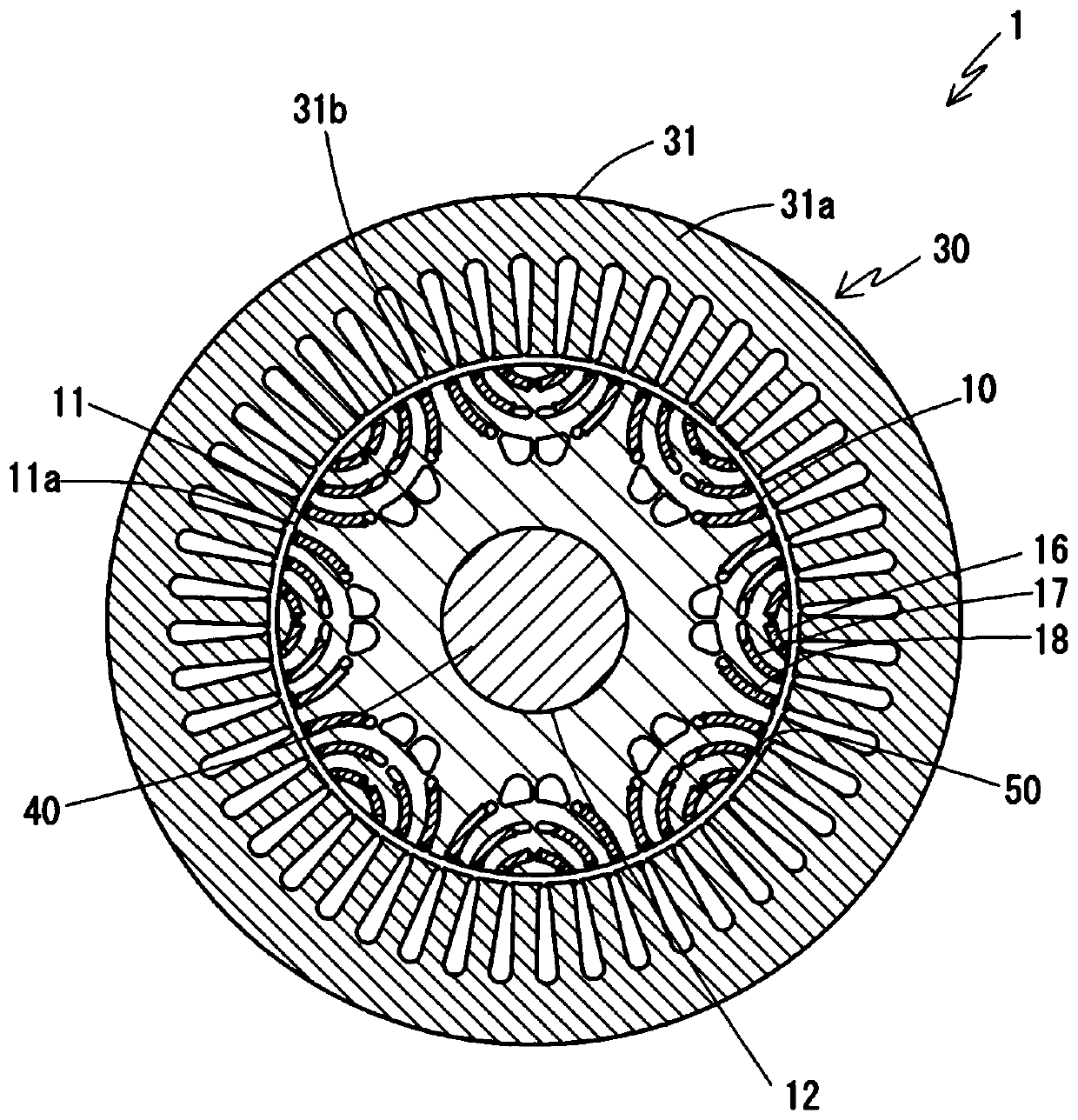
[0067] figure 1 A rotating electric machine 1 according to an embodiment of the present invention is schematically shown. The rotating electrical machine 1 includes a permanent magnet rotor 10 according to an embodiment of the present invention. Although this description will be directed to the case where the rotary electric machine 1 is a motor, the same configuration applies to the case where the rotary electric machine 1 is a generator.

[0068] The rotating electric machine 1 is configured as an internal permanent magnet (IPM) motor. The motor 1 includes a stator 30 shaped like a hollow cylinder and a rotor (permanent magnet rotor) 10 arranged concentrically with the stator 30 in the hollow space of the stator ...


PUM


Abstract

The present invention provides a permanent magnet rotor capable of reducing a harmonic component of a waveform of a magnetic flux density distribution formed in an air gap of a rotary electric machine, and a rotary electric machine having such a permanent magnet rotor.

Description

technical field [0001] This invention relates to permanent magnet rotors and rotating electrical machines. More particularly, the present invention relates to a permanent magnet rotor in which permanent magnets are embedded in a rotor core and a rotating electrical machine having such a permanent magnet rotor. Background technique [0002] Rotating electric machines using permanent magnet rotors such as internal permanent magnets (IPM) are expected to have small torque ripple that causes vibration and noise during operation and iron loss that lowers motor efficiency. For this reason, it is effective to bring the waveform of the magnetic flux density distribution formed in the air gap between the permanent magnet rotor and the stator close to a sine wave, thereby reducing the harmonic components of the waveform. [0003] For example, Patent Document 1 specifies the relationship between the size of the permanent magnets of the corresponding layers and the residual magnetic fl...

Claims


Application Information

Patent Timeline
IPC IPC(8): H02K1/27
CPCH02K1/2766H02K2213/03
Inventor 薮见崇生加纳善明
Owner DAIDO ELECTRONICS CO LTD
Why Eureka
Try Eureka