Control circuit of BUCK convertor

A control circuit and converter technology, applied in control/regulation systems, DC power input conversion to DC power output, instruments, etc., can solve the problems of low light load efficiency, surplus energy loss, etc.

Inactive Publication Date: 2019-10-29
XIAN YIPU COMM TECH
View PDF8 Cites 4 Cited by
  • Summary
  • Abstract
  • Description
  • Claims
  • Application Information

AI Technical Summary

Problems solved by technology

[0004] In the light-load mode of the BUCK converter, the inductor L current will appear, and the inductor L current will discharge to the ground through the second switch tube Q2, resulting in power loss; the first switch tube Q1 will gradually reduce the tube voltage drop during the turn-on process, and the loa

Method used


Image

  • Control circuit of BUCK convertor
  • Control circuit of BUCK convertor
  • Control circuit of BUCK convertor

Examples


Embodiment Construction

[0038] Reference will now be made in detail to the exemplary embodiments, examples of which are illustrated in the accompanying drawings. When the following description refers to the accompanying drawings, the same numerals in different drawings refer to the same or similar elements unless otherwise indicated. The implementations described in the following exemplary examples do not represent all implementations consistent with the present invention. Rather, they are merely examples of apparatuses and methods consistent with aspects of the invention as recited in the appended claims.

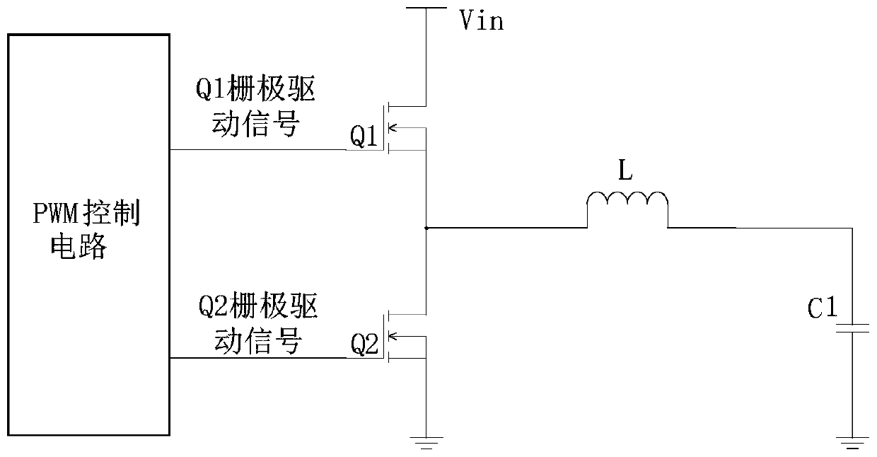
[0039] The invention provides a control circuit of a BUCK converter. The BUCK converter has the function of step-down conversion in the same direction, that is, the polarity of the input voltage and the output voltage are the same, and the output voltage is theoretically less than or equal to the input voltage.

[0040] figure 1 A schematic diagram of the structure of the BUCK converter, such a...


PUM


Abstract

The invention provides a control circuit of a BUCK converter. The control circuit of the BUCK converter comprises a voltage comparison circuit and an on-off control circuit. The voltage comparison circuit compares a detection voltage with a preset voltage and outputs a comparison result to the on-off control circuit. The current value of the preset voltage can charge a junction capacitance voltageof a second switching tube Q2 of the BUCK converter to be larger than or equal to the input voltage of the BUCK converter. When the detection voltage is larger than or equal to the preset voltage, the on-off control circuit controls the second switching tube Q2 to be turned off, an inductor L current continues to charge the Q2 junction capacitor, and finally the voltage of the Q2 junction capacitor is equal to the input voltage Vin. When the voltage of the Q2 junction capacitor is equal to the input voltage Vin, the drain-source voltage of the Q1 is zero, the turn-on time of the next period of the Q1 is just reached, and the tube voltage of the Q1 is reduced to zero, so that the turn-on of the zero-point voltage reduces the turn-on loss, and the efficiency of the BUCK converter is improved.

Description

technical field [0001] The invention relates to the technical field of switching power supplies, in particular to a control circuit of a BUCK converter. Background technique [0002] Switching direct current-direct current (DC-DC for short) converters are more and more widely used in the fields of computers, automation or electronic instruments due to their advantages of stable output voltage and high efficiency. The BUCK converter is a common DC-DC converter, and the BUCK converter is also called a step-down converter. [0003] figure 1 is a schematic diagram of a BUCK converter, such as figure 1 As shown, the BUCK converter includes a first switch tube Q1, a second switch tube Q2, an inductor L, a first capacitor C1 and a control circuit. The control circuit is used to drive the switch tubes Q1 and Q2 to conduct alternately in a complementary manner. When Q1 is closed and Q2 is disconnected, the input voltage charges the first capacitor C1 through the inductor L; when ...

Claims


Application Information

Patent Timeline
IPC IPC(8): H02M3/156
CPCH02M3/156H02M1/0048Y02B70/10
Inventor 刘晨光
Owner XIAN YIPU COMM TECH
Why Eureka
Try Eureka