Two-stage ammonia-spraying combined denitration system and denitration method

A technology of denitrification and jet mixing, applied in separation methods, chemical instruments and methods, gas treatment, etc., can solve the problems of NH3 escape concentration exceeding the standard, difficult to exceed 90%, poor efficiency adjustability, etc., to reduce denitrification pressure and operating costs Low, simple system effect

Pending Publication Date: 2019-11-01
HUADIAN ELECTRIC POWER SCI INST CO LTD
View PDF14 Cites 1 Cited by
  • Summary
  • Abstract
  • Description
  • Claims
  • Application Information

AI Technical Summary

Problems solved by technology

However, limited by the uniformity of the flue gas flow field and the uniformity of the injected reducing agent and NOx mixture, the denitrification efficiency of this technology alone is generally difficult to exceed 90%. Too high efficiency will easily lead to excessive NH3 escape concentration, resulting in tail air preheater blockage
[0004] Another example is CN 106390717 A - "a denitrification flue for SCR and SNCR combined denitrification", which divides the flue into several separate flue sections in cross-section by setting a partition structure in the flue in front of the SCR denitrification reactor. Each separate flue is equipped with a flue gas mixer at the entrance, and an independently controlled denitrification reducing agent injection device is installed at the outlet. The purpose is still to solve the flow field uniformity problem of the traditional SCR denitrification technology, but The corresponding flue gas resistance is high, and the efficiency of the upstream SNCR denitrification device is poorly adjustable

Method used


Image

  • Two-stage ammonia-spraying combined denitration system and denitration method

Examples


Embodiment Construction

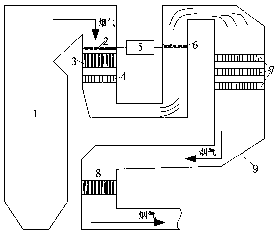
[0019] The present invention will be further described in detail below in conjunction with the accompanying drawings and examples. The following examples are explanations of the present invention and the present invention is not limited to the following examples.

[0020] Example.

[0021] see figure 1 It should be noted that the structures, proportions, sizes, etc. shown in the drawings attached to this specification are only used to match the content disclosed in the specification, for those who are familiar with this technology to understand and read, and are not used to limit the present invention Therefore, it has no technical substantive meaning, and any modification of structure, change of proportional relationship or adjustment of size shall still fall into the within the scope covered by the technical content disclosed in the present invention. At the same time, if terms such as "upper", "lower", "left", "right", "middle" and "one" are used in this specification, th...


PUM


Abstract

The invention relates to a two-stage ammonia-spraying combined denitration system and a denitration method, belonging to the fields of industrial waste gas purification and environmental protection and energy. The two-stage ammonia-spraying combined denitration system provided by the invention has a structure which is characterized by comprising a flue, and also comprising a boiler, a first-stagereducing agent jet mixing device, an economizer, a first-stage flue SCR denitration reactor, a reducing agent supply system, a second-stage reducing agent jet mixing device, a second-stage independentSCR denitration reactor and an air preheater, wherein the boiler is connected with the inlet of the flue; the first-stage reducing agent jet mixing device, the economizer, the first-stage flue SCR denitration reactor, the second-stage reducing agent jet mixing device, the second-stage independent SCR denitration reactor and the air preheater are successively arranged in the flue along the flowingdirection of flue gas; and the first-stage reducing agent jet mixing device and the second-stage reducing agent jet mixing device are connected with the reducing agent supply system. Compared with the prior art, the two-stage ammonia-spraying combined denitration system provided by the invention has the advantages of high denitration efficiency, simple system, low operation cost, high reducing agent utilization rate, extensive application prospect, etc.

Description

technical field [0001] The invention relates to a two-stage ammonia injection combined denitrification system and a denitrification method, belonging to the fields of industrial waste gas purification, environmental protection and energy. Background technique [0002] my country's coal-based energy structure will not change for a long time. Therefore, controlling the emission of coal-fired flue gas pollutants is an important task for my country's air pollution control. At present, the most widely used flue gas denitrification technology in coal-fired power plants is selective catalytic reduction (SCR) technology. This technology has the advantages of maturity, stability and economy. However, its denitrification efficiency is limited by the NH3 escape control index, and the general design does not exceed 90%. . Under high-efficiency operating conditions, it often leads to problems such as increased consumption of denitrification reducing agents, excessive NH3 escape concentr...

Claims


Application Information

Patent Timeline
Patent Type & Authority Applications(China)
IPC IPC(8): B01D53/86B01D53/56
CPCB01D53/8631B01D2258/0283B01D2251/2062
Inventor 张杨李沙戴瑜马俊飞徐克涛郭博闻朱跃
Owner HUADIAN ELECTRIC POWER SCI INST CO LTD
Why Eureka
Try Eureka