Electronic component

一种电子元器件、导电端子的技术,应用在电气元件、电固体器件、电阻器零部件等方向,能够解决难屏蔽板安装规定间隔、难导电板851等问题,达到可靠性能、可靠性和耐久性提高、制造成本降低的效果

Active Publication Date: 2019-11-01
MOLEX INC
View PDF19 Cites 0 Cited by
  • Summary
  • Abstract
  • Description
  • Claims
  • Application Information

AI Technical Summary

Problems solved by technology

[0008] However, in conventional electronic components, although the conductive plates 851 are held by the base 811, since the base 811 is only a part for curing the resin to form a predetermined shape, it is difficult to make the interval between adjacent conductive plates 851 In addition, it is difficult to install the shielding plate on the conductive plate 851 to maintain a specified interval between the two.
In recent years, with the miniaturization of various electrical equipment and electronic equipment, the electronic components mounted on the substrate of the electrical equipment and electronic equipment also tend to be miniaturized; In the case of an electronic component of the structure, when miniaturization, because it is difficult to strictly manage the size of the base 811 formed by curing the resin, it is further difficult to make the interval between the adjacent conductive plates 851 and the shielding plate and The interval between the conductive plates 851 is strictly kept at a specified minute size

Method used


Image

  • Electronic component
  • Electronic component
  • Electronic component

Examples


Embodiment Construction

[0059] Embodiments will be described in detail below with reference to the accompanying drawings.

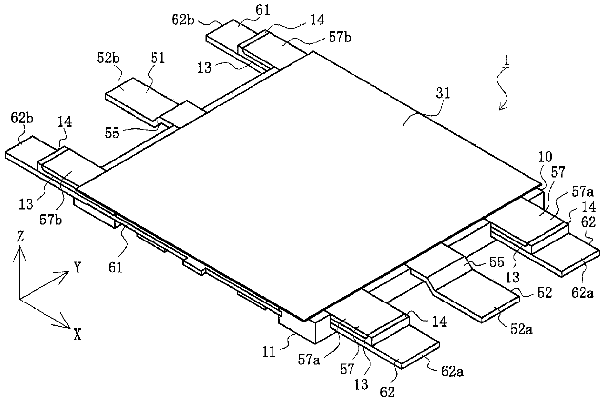
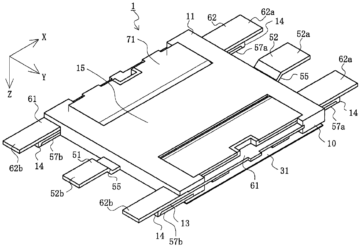
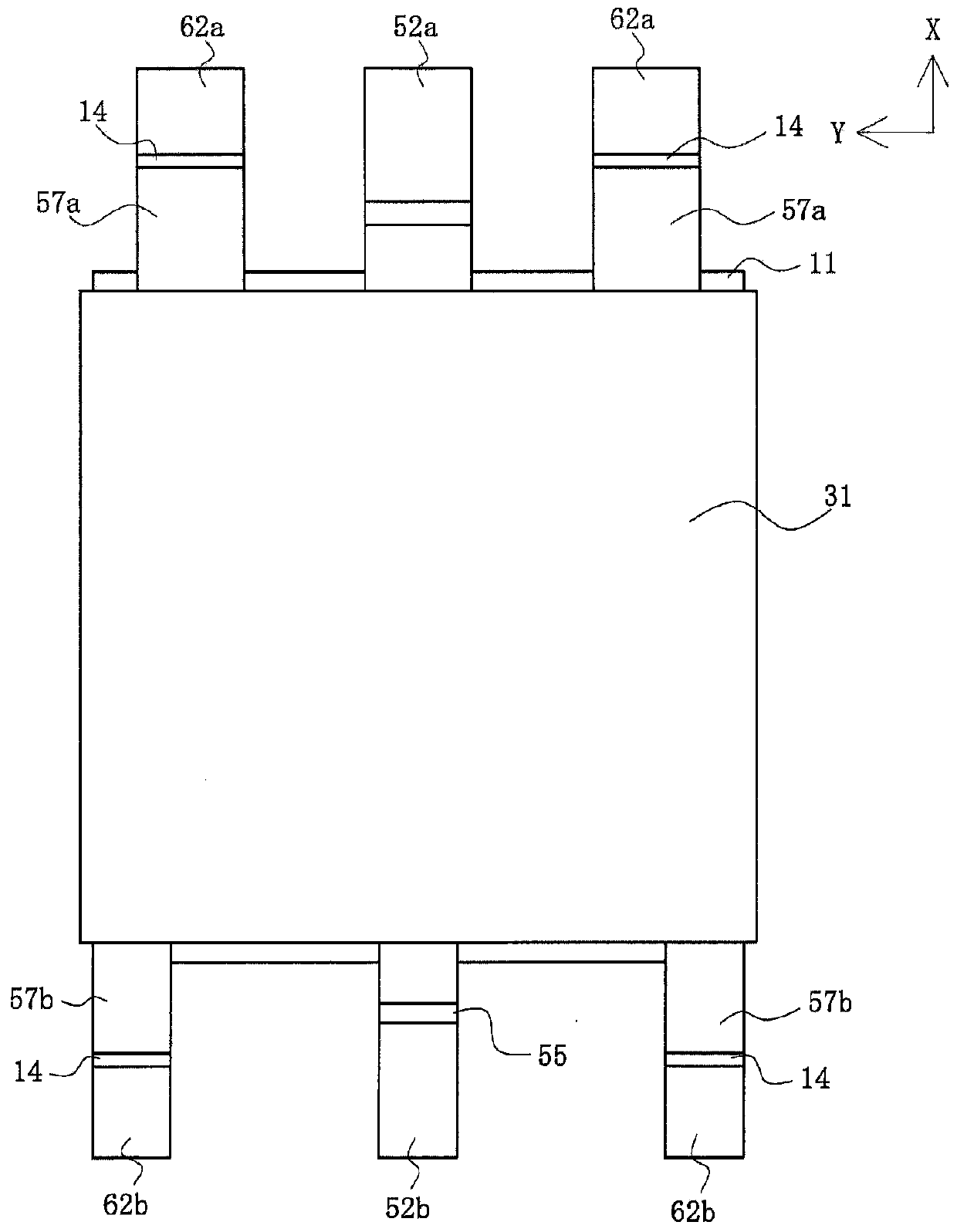
[0060] Figure 1A , Figure 1B is a perspective view showing an electronic component according to this embodiment, Figure 2A , Figure 2B is a first two-sided view of the electronic component according to the present embodiment, Figure 3A , Figure 3B is a second two-sided view of the electronic component according to the present embodiment, Figure 4A , Figure 4B is a perspective view showing a state in which the adhesive sheet is removed of the electronic component according to the present embodiment, Figure 5A , Figure 5B is a first two-sided view showing the state of the electronic component according to the embodiment after removing the adhesive sheet, and Figure 6A , Figure 6B is a second double side view showing the state of the electronic component according to the present embodiment after removing the adhesive sheet. Please be aware of, Figure 1A and ...


PUM


Abstract

The invention discloses an electronic component that can reliably exhibit the desired performance even when miniaturized, in addition to having high reliability, low manufacturing cost, and high durability. An electronic component is provided that includes multiple conductive terminals and an insulator integrated with the conductive terminals. A leg part possessed by one of the conductive terminals and a leg part possessed by another one of the conductive terminals are disposed so as to vertically overlap each other. The leg part possessed by one of the conductive terminals and the leg part possessed by another one of the conductive terminals have different lengths, and the tip of the shorter leg part of the two is covered by a thick part of the insulator.

Description

technical field [0001] The invention relates to an electronic component. Background technique [0002] Conventionally, chip-shaped electronic components including various elements such as resistors are mounted on a substrate such as a printed circuit board (see Patent Document 1, for example). [0003] Figure 14A , Figure 14B is a view showing a conventional electronic component. It should be noted that, in the figures, figure A is a perspective view of an electronic component, and figure B is a perspective view of a conductive plate. [0004] In the figure, 801 is a jumper chip, which is a kind of electronic component and is mounted on the surface of a substrate not shown in the figure. The jumper chip 801 is provided with a plurality of conductive plates 851 and a base 811 for wrapping and encapsulating a part near the center of the conductive plates 851 . [0005] The conductive plate 851 is an elongated plate member made of conductive metal such as copper alloy, an...

Claims


Application Information

Patent Timeline
Patent Type & Authority Applications(China)
IPC IPC(8): H01C13/02H01C1/02H01C1/032H01C1/14H01C1/16
CPCH01C13/02H01C1/02H01C1/032H01C1/14H01C1/16H01L23/3107H01L23/49534H01L23/552H01L23/49537H01L24/06H01L23/647H01L2224/73215H01L23/28H01L23/49838
Inventor 新津俊博野川义辉
Owner MOLEX INC
Why Eureka
Try Eureka