

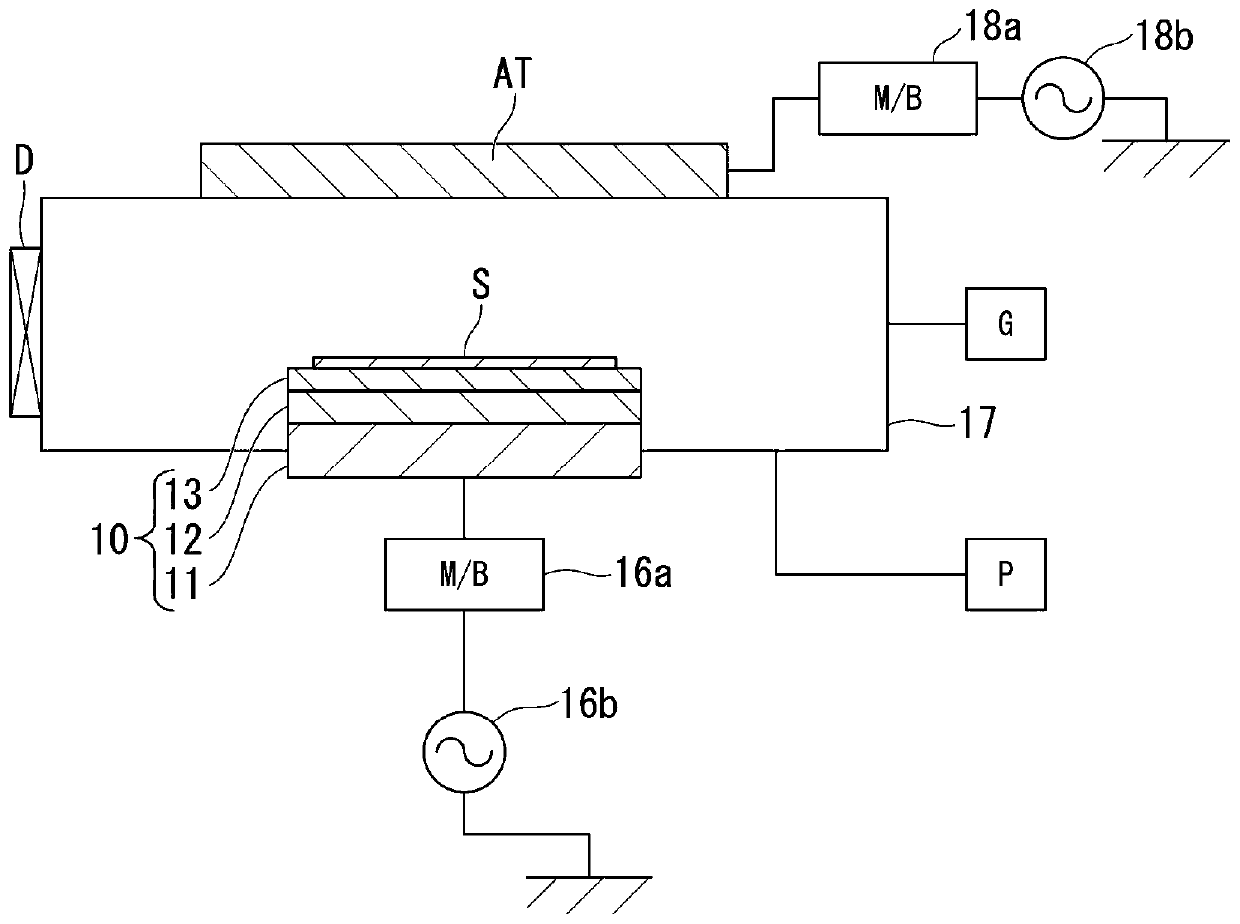
Apparatus for treating object to be treated
A technology of the object to be processed and the processing device, applied in the direction of plasma, semiconductor/solid-state device manufacturing, discharge tube, etc., can solve the problems of reducing the optimal range, the influence of the introduction amount or pressure, and the loss of the optimal range.
- Summary
- Abstract
- Description
- Claims
- Application Information
AI Technical Summary
Problems solved by technology
Method used
Image

Examples
experiment example 1
[0132] Figure 20 It is a list which shows the evaluation result of Experimental Example 1 (case which does not have a pad part). Figure 20 (a) shows a distribution graph showing the etching rate. Figure 20 (b) shows a graph showing the normalized etching rate. Figure 20 (c) shows the insertion position of the pad part. Figure 20 D shows the effect. Figure 20 The four angles (0°, 45°, 90°, 315°) in (b) are Figure 20 The direction in which the etching rate is measured in the substrate (object to be processed) shown in (a).
[0133] In the case of Experimental Example 1, by Figure 20 It is clear from (b) that the normalized etch rates are very different in the four angles. That is, it can be seen that in Experimental Example 1, the angular dependence of the etching rate of the object to be processed is strong, and the distribution of the etching rate in the plane of the substrate (object to be processed) is not uniform.
experiment example 2
[0135] Figure 21 It is a list which shows the evaluation result of Experimental Example 2 (case where the pad part was arrange|positioned on the whole circumference). Figure 21 (a) shows a distribution graph showing the etching rate. Figure 21 (b) shows a graph showing the normalized etching rate. Figure 21 (c) shows the insertion position of the pad part. Figure 21 (d) shows the effect. Figure 21 The four angles (0°, 45°, 90°, 315°) in (b) are Figure 21 The direction in which the etching rate is measured in the substrate (object to be processed) shown in (a).
[0136] In the case of Experimental Example 2, by Figure 21 It is clear from (b) that the normalized etch rates are very different in the four angles. That is, it can be seen that the angular dependence of the etching rate of the object to be processed is strong, and the distribution of the etching rate in the plane of the substrate (object to be processed) is not uniform. In Experimental Example 2, it wa...
experiment example 3
[0138] Figure 22 It is a list showing the evaluation results of Experimental Example 3 (the case where the pad portion is arranged on the right semicircular portion). Figure 22 (a) shows a distribution graph showing the etching rate. Figure 22 (b) shows a graph showing the normalized etching rate. Figure 22 (c) shows the insertion position of the pad part. Figure 22 (d) shows the effect.
[0139] In the case of Experimental Example 3, by Figure 22 (b) clearly shows that the normalized etch rate differs in the four angles. That is, in Experimental Example 3, it can be seen that although the angular dependence of the etching rate of the object to be processed is weaker than that of Experimental Examples 1 and 2, the distribution of the etching rate in the substrate surface is still uneven. It was confirmed that, as in Experimental Example 3, the pad portion was placed on the Figure 22 Also in the case of the semicircular portion on the right side in (c), as in Exper...
PUM
 Abstract
Description
Claims
Application Information