Image quality compensation device, optical system and photoetching machine

A compensation device and image quality technology, applied in the field of photolithography, can solve the problems of difficult manufacturing, high cost, unfavorable generalization and mass production and use of image quality compensation devices, etc.

Active Publication Date: 2020-07-07
SHANGHAI MICRO ELECTRONICS EQUIP (GRP) CO LTD
View PDF9 Cites 1 Cited by
  • Summary
  • Abstract
  • Description
  • Claims
  • Application Information

AI Technical Summary

Problems solved by technology

In the optical system image quality compensation device provided by the prior art, the structure of the fine-tuning mechanism is complicated, the manufacture is difficul

Method used


Image

  • Image quality compensation device, optical system and photoetching machine
  • Image quality compensation device, optical system and photoetching machine
  • Image quality compensation device, optical system and photoetching machine

Examples


Embodiment Construction

[0059] The present invention will be further described in detail below in conjunction with the accompanying drawings and embodiments. It should be understood that the specific embodiments described here are only used to explain the present invention, but not to limit the present invention. In addition, it should be noted that, for the convenience of description, only some structures related to the present invention are shown in the drawings but not all structures.

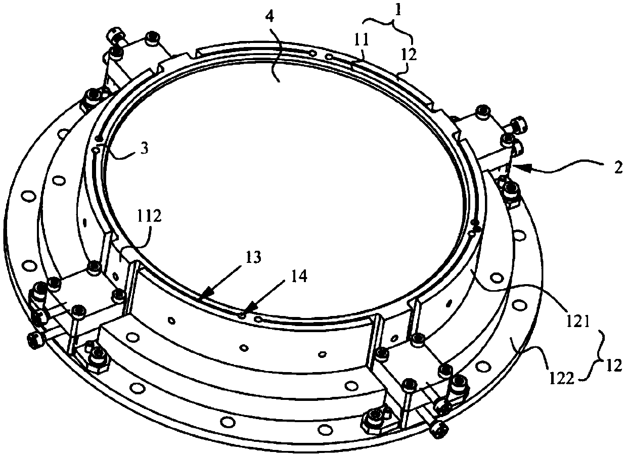
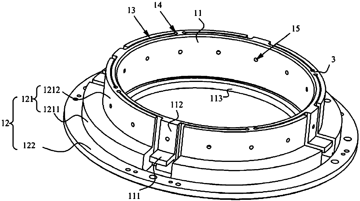
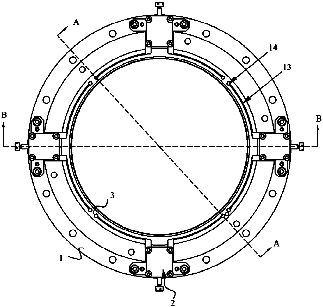
[0060] figure 1 Schematic diagram of the structure of the image quality compensation device provided by the embodiment of the present invention, such as figure 1 As shown, the present embodiment provides an image quality compensating device, which is used to fine-tune the surface shape of the deformable mirror 4, thereby compensating the image quality of the deformable mirror 4 and the optical system where the deformable mirror 4 is located, and improving the shape of the deformable mirror 4 and the optical system...


PUM

PropertyMeasurementUnit
Pitchaaaaaaaaaa

Abstract

The invention belongs to the technical field of photoetching, and particularly discloses an image quality compensation device, an optical system and a photoetching machine. The image quality compensation device comprises: a lens base, wherein the lens base comprises an annular adjusting base, the inner wall of the adjusting base is used for being connected with a deformable mirror, and a pluralityof adjusting bosses are arranged on the outer wall of the adjusting base at intervals in the circumferential direction; a fine adjustment mechanism that can drive the adjusting bosses to move in theaxial direction of the adjusting base; and restraining parts that are arranged between every two adjacent adjusting bosses, and are connected with the outer wall of the adjusting base and used for limiting movement of the adjusting base. The optical system comprises the image quality compensation device, and the photoetching machine comprises the optical system. The image quality compensation device, the optical system and the photoetching machine are simple in structure, convenient to adjust and low in cost.

Description

technical field [0001] The invention relates to the technical field of photolithography, in particular to an image quality compensation device, an optical system and a photolithography machine. Background technique [0002] As the core component of the lithography machine, the projection objective lens is one of the most sophisticated and complex optical systems in modern times. With the development of the miniaturization of integrated circuits, while the size of the chip continues to shrink, higher requirements are put forward for the wave aberration index of the projection objective lens. Research and development of lithographic projection objective lens with good image quality compensation ability has become one of the research hotspots at home and abroad. [0003] The active deformable mirror group compensates the aberration of the optical system through the change of its own lens surface shape, and is widely used in various lithography projection objectives. There are ...

Claims


Application Information

Patent Timeline
IPC IPC(8): G02B26/08G03F7/20
CPCG02B26/0825G03F7/70266
Inventor 杨若霁王彦飞姜文庆
Owner SHANGHAI MICRO ELECTRONICS EQUIP (GRP) CO LTD
Why Eureka
Try Eureka