Eureka AIR delivers breakthrough ideas for toughest innovation challenges, trusted by R&D personnel around the world.

Casting waste gas treatment equipment

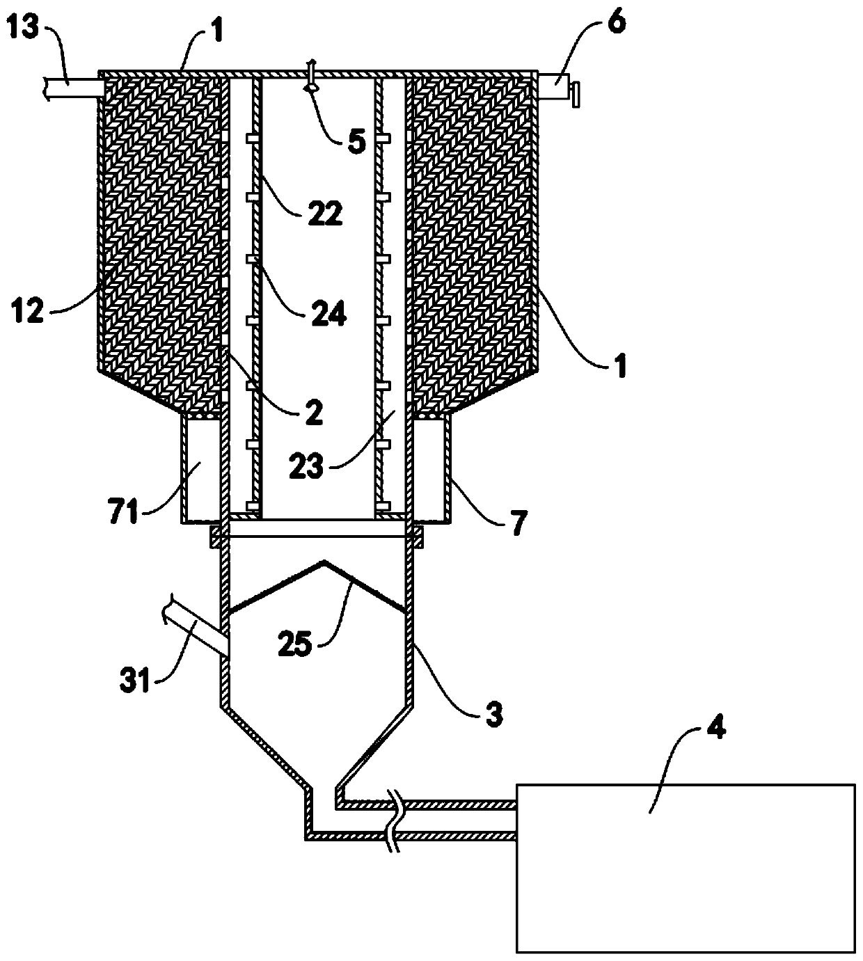
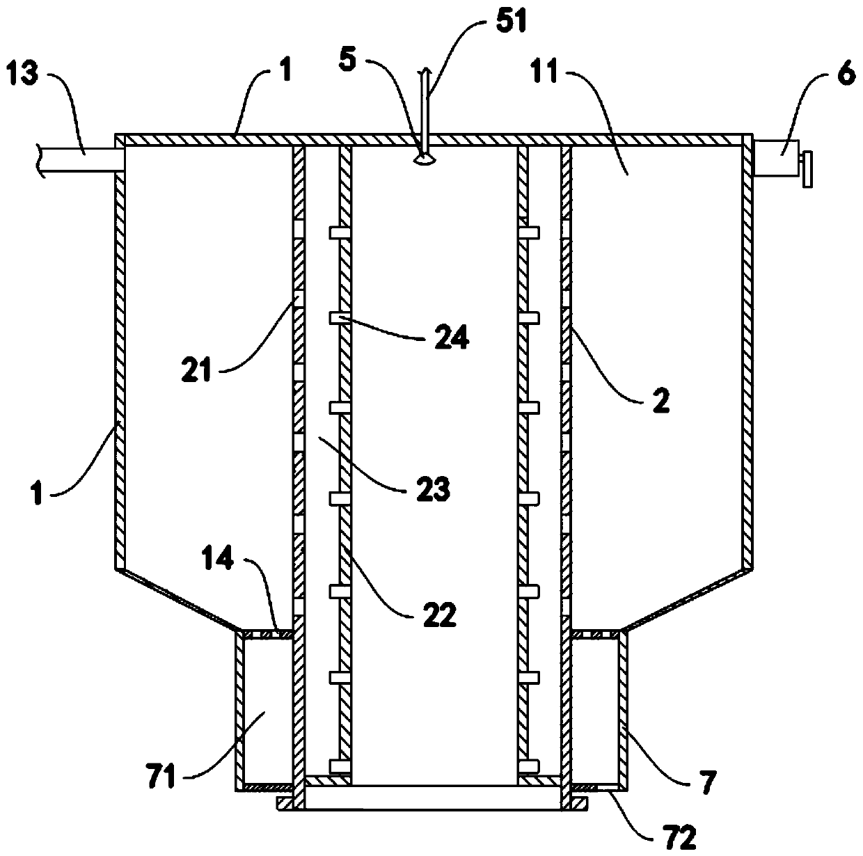
A waste gas treatment equipment and airflow technology, applied in the direction of degassed water/sewage treatment, gaseous effluent wastewater treatment, water/sewage multi-stage treatment, etc., can solve the problems of deteriorating production environment, single function, large floor area, etc. Achieve the effect of reducing secondary environmental pollution, improving spray purification effect, and low noise of equipment operation

Pending Publication Date: 2019-11-05
TONGLIN CASTING IND
View PDF0 Cites 0 Cited by
  • Summary
  • Abstract
  • Description
  • Claims
  • Application Information

AI Technical Summary

Problems solved by technology

[0002] A large amount of smoke, dust and heat will be generated in the casting production process, especially in the equipment manufacturing industry, the relatively common resin-coated sand is currently used, and a large amount of formaldehyde and phenol are volatilized and cracked in the process of core making and high-temperature pouring. These toxic and harmful gases not only deteriorate the production environment, but also cause serious pollution to the atmosphere around the factory area. Effective treatment must be carried out to ensure that relevant national emission standards are met.
Casting exhaust gas purification needs to be carried out in several steps. Most of the existing related purification equipment has simple structure and single function, and has disadvantages such as low purification efficiency, high operating noise, and large floor space.

Method used


Image

  • Casting waste gas treatment equipment
  • Casting waste gas treatment equipment
  • Casting waste gas treatment equipment

Examples


Embodiment Construction

[0022] In order to make the purpose, technical solutions and advantages of the embodiments of the present invention clearer, the technical solutions in the embodiments of the present invention will be clearly and completely described below in conjunction with the drawings in the embodiments of the present invention. Obviously, the described embodiments It is a part of embodiments of the present invention, but not all embodiments. The components of the embodiments of the invention generally described and illustrated in the figures herein may be arranged and designed in a variety of different configurations.

[0023] Accordingly, the following detailed description of the embodiments of the invention provided in the accompanying drawings is not intended to limit the scope of the claimed invention, but merely represents selected embodiments of the invention. Based on the embodiments of the present invention, all other embodiments obtained by persons of ordinary skill in the art wi...


PUM


Abstract

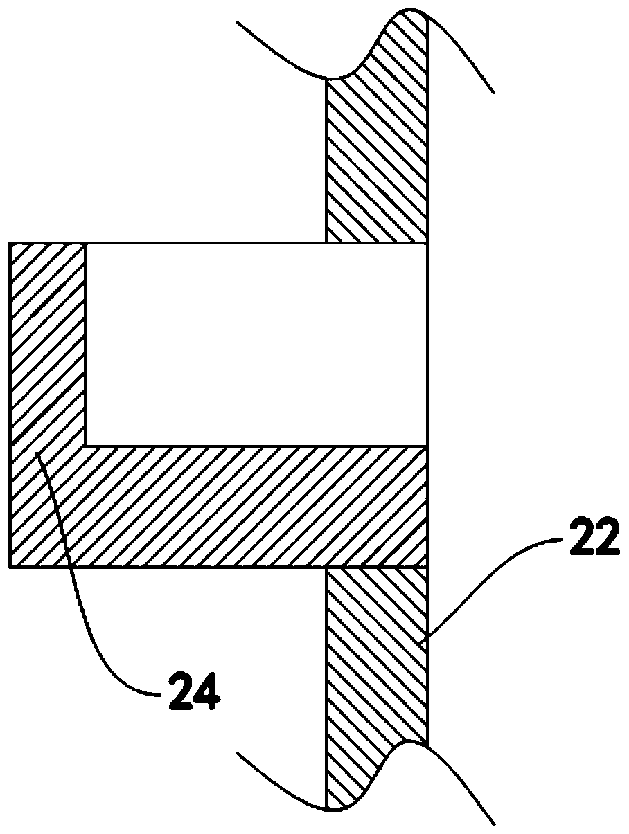
The invention discloses casting waste gas treatment equipment, which comprises an outer shell, an inner shell, a water-gas separation tank, a grit chamber, a spray head and a vibration mechanism, wherein the upper end of the inner shell is fixedly connected with the top of the outer shell; the lower end of the inner shell penetrates through the bottom of the outer shell and extends out of the outer shell; the outer shell and the inner shell form a containing cavity together; and metal wire balls are filled in the containing cavity; the water-gas separation tank is arranged below the inner shell, the top of the water-gas separation tank is communicated with the bottom of the inner shell, and the bottom of the water-gas separation tank is communicated with the water inlet end of the grit chamber. A spraying device is arranged in primary dust removal equipment, so that the occupied area is reduced, the contact efficiency of an airflow and a vertically moving water flow is greatly improved, the spraying purification effect is improved, the equipment operation noise is low, and the secondary environmental pollution is greatly reduced.

Description

technical field [0001] The invention belongs to the technical field of waste gas treatment equipment, in particular to casting waste gas treatment equipment. Background technique [0002] A large amount of smoke, dust and heat will be generated in the casting production process, especially in the equipment manufacturing industry, the relatively common resin-coated sand is currently used, and a large amount of formaldehyde and phenol are volatilized and cracked in the process of core making and high-temperature pouring. These toxic and harmful gases not only deteriorate the production environment, but also cause serious pollution to the atmosphere around the factory area. Effective treatment must be carried out to ensure that the relevant national emission standards are met. Purification of foundry exhaust gas needs to be carried out in several steps. Most of the existing related purification equipment has simple structure and single function, and has disadvantages such as lo...

Claims


Application Information

Patent Timeline
Patent Type & Authority Applications(China)
IPC IPC(8): B01D50/00B01D53/18C02F9/02C02F103/18
CPCB01D53/185C02F1/20C02F1/52C02F2103/18B01D50/60
Inventor 聂越赵红霞袁江
Owner TONGLIN CASTING IND
Why Eureka
Eureka Blog
Learn More