Flexible bending machine based on servo drive

A technology of servo drive and bending machine, which is applied in the field of flexible bending machine, can solve the problems of frame and processing material damage, high operating cost, low processing accuracy, etc., meet the requirements of reducing installation accuracy, avoid hydraulic oil pollution, The effect of improving machining accuracy

Pending Publication Date: 2019-11-05
江苏弘东工业自动化有限公司
View PDF0 Cites 2 Cited by
  • Summary
  • Abstract
  • Description
  • Claims
  • Application Information

AI Technical Summary

Problems solved by technology

[0003] 1. Since the side plate of the prior art bending machine is connected to the oil cylinder and the lower beam, it is inevitable that the traditional bending machine needs to design a throat on the side plate so that the bending length of the plate can be stretched into the throat to be bent. Therefore, the depth of the throat and other dimensions limit the size of the plate that can be processed
[0004] 2. Since the driving method of the prior art is driven by a hydraulic cylinder, the processing accuracy is not high, and the hydraulic system needs frequent maintenance, and there may be problems such as hydraulic oil pollution; and the driving of the hydraulic system is controlled by an AC motor and a valve group. The AC motor must be kept running at all times, with high power consumption and high operating costs
[0005] 3. Due to the rigid connection of the components in the prior art, it cannot be adjusted, and the installation accuracy of the components is high. When the moving parts on the left and right sides are not synchronized during work, it may cause damage to the frame and processing materials. cause damage

Method used


Image

  • Flexible bending machine based on servo drive
  • Flexible bending machine based on servo drive
  • Flexible bending machine based on servo drive

Examples


Embodiment Construction

[0031] The present invention will be further described below in conjunction with the accompanying drawings and specific embodiments.

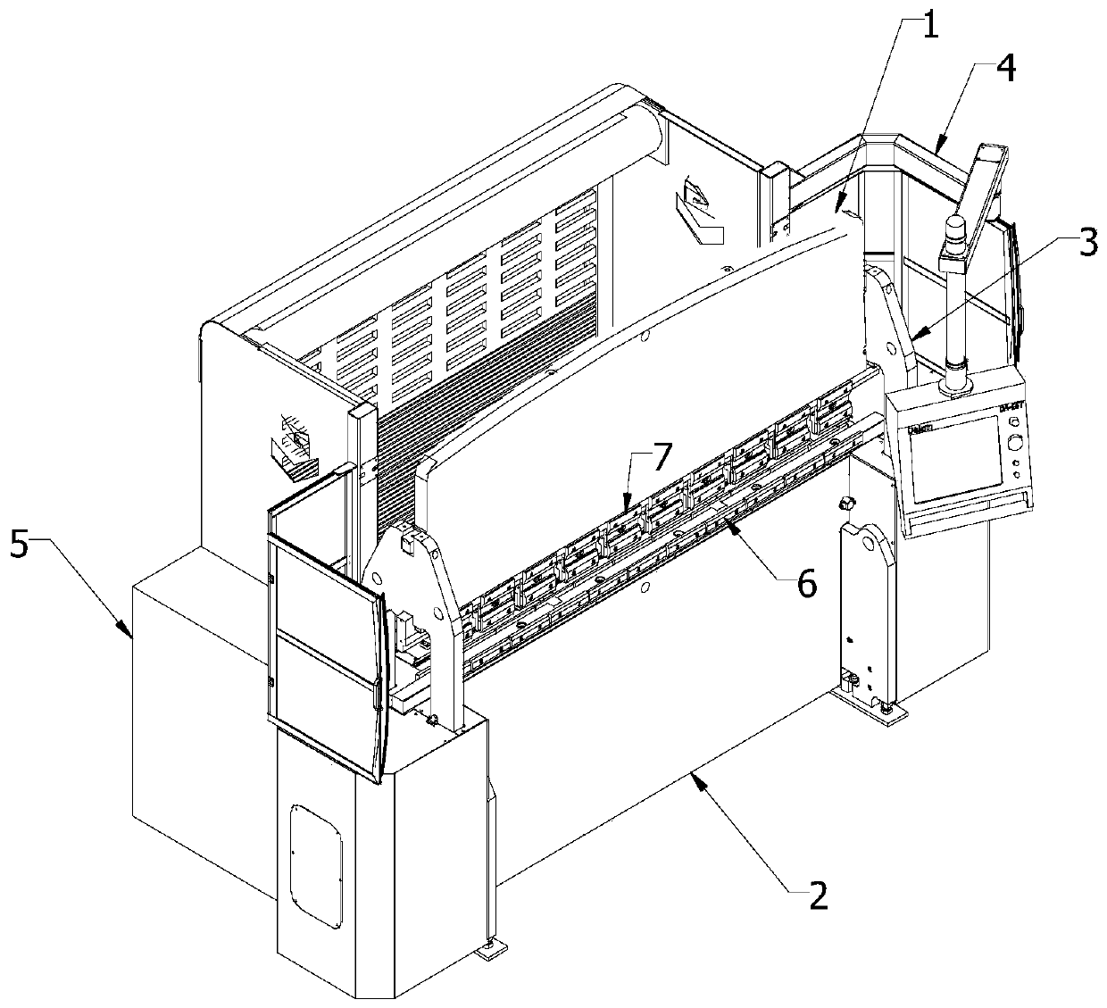
[0032] Please see attached figure 1 , attached Figure 8 And attached Figure 9, a flexible bending machine based on servo drive, including an upper beam assembly structure 1, a lower beam assembly structure 2, a frame assembly structure 3, an outer frame assembly structure 4, an electric cabinet box 5, a workbench 6, The clamp block 7 and the back gauge assembly structure 8; the upper beam assembly structure 1 and the lower beam assembly structure 2 are installed on the frame assembly structure 3 and move up and down, and the frame assembly structure 3 is installed on the outer frame assembly structure. On the assembly structure 4, the workbench 6 is installed on the lower beam 21 of the lower beam assembly structure 2 through screws, the clamp block 7 is installed on the upper beam 11 of the upper beam assembly structure 1, the electrical c...


PUM


Abstract

The invention discloses a flexible bending machine based on servo drive. The flexible bending machine based on servo drive comprises an upper beam general assembly structure (1), a lower beam generalassembly structure (2), a machine frame general assembly structure (3), an external frame general assembly structure (4), an electric cabinet (5), a workbench (6), clamping blocks (7) and a rear material baffle general assembly structure (8). A first flexible connection assembly and a second flexible connection assembly are symmetrically arranged at two ends of an upper beam (11). The machine frame general assembly structure (3) comprises a first side plate (31), a second side plate (335), side supporting arm movement assemblies, a lower beam installation and movement assembly, an upper beam movement assembly and servo drive assemblies. According to the flexible bending machine based on servo drive, a servo motor drives side supporting arms to drive the upper beam to move up and down so asto achieve plate bending operation, no throat opening needs to be arranged, the problem that the machining size is limited is solved, the machining accuracy can be improved, and the power consumptionand the pollution can be reduced.

Description

technical field [0001] The invention relates to a bending processing machine, in particular to a flexible bending machine based on servo drive. Background technique [0002] A bending machine is a processing machine that bends sheet metal. The traditional bending machine uses the hydraulic cylinder to drive the upper beam to move up and down to fold the plate. The frame structure of the traditional bending machine is roughly the same: it is basically composed of the upper beam, the lower beam, the left and right side plates and the oil cylinder. . There are following deficiencies in the bending machine of prior art: [0003] 1. Since the side plate of the prior art bending machine is connected to the oil cylinder and the lower beam, it is inevitable that the traditional bending machine needs to design a throat on the side plate so that the bending length of the plate can be stretched into the throat to be bent. Therefore, the depth of the throat and other dimensions limit...

Claims


Application Information

Patent Timeline
Patent Type & Authority Applications(China)
IPC IPC(8): B21D5/02
CPCB21D5/02
Inventor 林忠许铮吴达通曹宇付红芝
Owner 江苏弘东工业自动化有限公司
Why Eureka
Try Eureka