An Array Rod Laser Amplifier

A laser amplifier and array technology, used in lasers, laser devices, laser parts, etc., can solve the problems of inability to make large-diameter gain media, complex auxiliary circulation system structure, uneven gain distribution, etc., to improve energy The utilization rate, thermal management effect is good, and the effect of improving the utilization rate of energy storage

Active Publication Date: 2019-05-17
SHANGHAI INST OF OPTICS & FINE MECHANICS CHINESE ACAD OF SCI
View PDF3 Cites 0 Cited by
  • Summary
  • Abstract
  • Description
  • Claims
  • Application Information

AI Technical Summary

Problems solved by technology

[0003] However, there are problems in the above-mentioned measures. For example, the growth size of the new gain medium crystal is limited, so it cannot be made into a large-diameter gain medium. The current mainstream application of Yb:YAG crystal, the patent 101338453 uses the pulling method to grow the diameter of about 35~50mm, literature [Xu X, Zhao Z, Zhao G, et al.Comparison of Yb:YAG crystals grownby CZ and TGT method[J].Journal of Crystal growth,2003,57(3):297-300. ] reported that the crystal size grown by the temperature gradient method is φ75mm×45mm, which shows the limitations of new laser crystal materials in high-power laser applications
[0004] Surface-cooled chip amplifiers have serious lateral ASE and parasitic oscillations in the chip structure, which will lead to uneven gain distribution and low energy storage efficiency. In order to suppress ASE, literature [Banerjee S, Ertel K, Mason P D, et al. DiPOLE:a 10J,10Hz cryogenic gas cooled multi-slab nanosecond Yb:YAG laser.[J].Optics Express,2015,23(15):19542-51.] reported the introduction of a Circle Cr 4+ : YAG wrapping to absorb lateral ASE, although this method is effective, but still needs to be optimized
In addition, chip amplifiers are mainly multi-chip air-cooled, and the multi-chip air-cooled structure also has the problem of complex structure of the auxiliary circulation system for high-speed clean airflow

Method used


Image

  • An Array Rod Laser Amplifier
  • An Array Rod Laser Amplifier
  • An Array Rod Laser Amplifier

Examples


Embodiment Construction

[0026] The present invention will be further described below in conjunction with the embodiments and accompanying drawings, but the protection scope of the present invention should not be limited thereby.

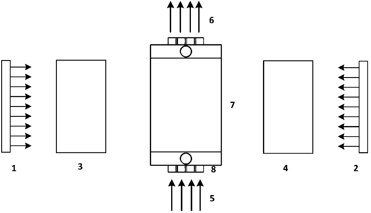
[0027] see first figure 1 , figure 1 It is a block diagram of the overall structure of the array rod laser amplifier of the present invention. Depend on figure 1 It can be seen that the array rod laser amplifier consists of four parts: pump source, coupling lens group, laser gain medium and mechanical structure. The pumping source includes two parallel and oppositely placed laser diodes 1, 2, the described coupling lens group is composed of two parallel and oppositely placed coupling lenses 3, 4, and the mechanical structure 7 has a positive effect on the laser gain The medium 8 provides a clamping and fixing effect. In the direction vertical and parallel to the side of the laser gain medium 8, there are light-transmitting windows 40 and 41 that are larger than the size ...


PUM


Abstract

The invention discloses an array-type rod-shaped laser amplifier, and the laser amplifier consists of a pumping source, a coupling lens group, a combined laser gain medium, and a mechanical structure. The laser amplifier employs the array-type small-diameter rod-shaped laser gain medium, so the laser amplifier solves a problem that the size of the laser gain medium is limited. Moreover, the number of rods can be adjusted according to the energy demands, so the laser amplifier is flexible. The horizontal side surfaces of laser gain medium rods are glued with materials which are capable of absorbing amplified spontaneous radiation and have thermal conductivity higher than that of a gain medium. Cooling liquid flow channels are disposed between the vertical side surfaces of laser gain medium rods, thereby improving the thermal management effect in the above mode. Through the reasonable design of the shape of the gain medium, the laser amplifier can reduce the impact from spontaneous radiation and parasitic oscillation. The laser amplifier is compact in structure, is simple in auxiliary circulating system, is good in reliability, and is high in efficiency.

Description

technical field [0001] The invention relates to the technical field of high-power repetition rate solid-state lasers, in particular to an array type rod laser amplifier. Background technique [0002] High-efficiency repetition-frequency solid-state laser technology is one of the main technical development directions of high-power laser drivers. However, severe thermal effects in the system limit the further improvement of the repetition rate of high-power laser drivers. Facing the problem of thermal effects in the system, the current solution to the repetition frequency solid-state laser mainly starts from the following aspects: 1. Use laser diode (LD) pumping instead of xenon lamp pumping to reduce the heat source in the gain medium; 2. Adopt A new type of gain medium replaces traditional glass with a crystal with higher thermal conductivity; 3. Adopt a new type of heat dissipation method to increase heat dissipation capacity, such as sheet amplifiers, slat amplifiers, etc...

Claims


Application Information

Patent Timeline
Patent Type & Authority Patents(China)
IPC IPC(8): H01S3/06H01S3/091H01S3/04H01S3/042H01S3/16H01S3/17H01S3/23
CPCH01S3/0407H01S3/042H01S3/061H01S3/091H01S3/1611H01S3/17H01S3/23
Inventor 王江峰陈亚林范薇黄庭瑞郭江涛
Owner SHANGHAI INST OF OPTICS & FINE MECHANICS CHINESE ACAD OF SCI
Why Eureka
Try Eureka