Inclined shaft common rail clamping rail man car

A rail-riding and ordinary technology, which is applied in the field of ordinary rail clamping rail-riding vehicles in inclined shafts, can solve the problems of additional installation of brakes and bending of long-wheelbase frames, and achieves compact structure, low renovation cost, and high safety performance. reliable effect

Pending Publication Date: 2019-11-08
CHANGZHOU DEV & MFR CENT
View PDF3 Cites 0 Cited by
  • Summary
  • Abstract
  • Description
  • Claims
  • Application Information

AI Technical Summary

Problems solved by technology

When the rail steering device is used, it can be effectively applied to undulating rails, yin and yang rails, and gauge changing rails, and can conveniently solve the problem of cornering of long-wheelbase frames. However, the brake of the rail car with the rail steering device installed need to be installed separately

Method used


Image

  • Inclined shaft common rail clamping rail man car
  • Inclined shaft common rail clamping rail man car
  • Inclined shaft common rail clamping rail man car

Examples


Embodiment 1

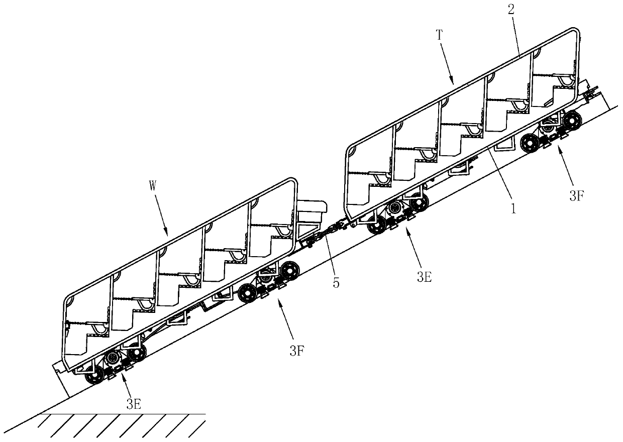
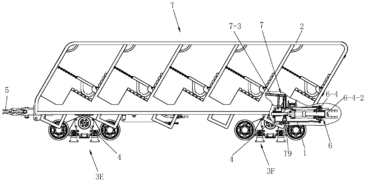
[0043] See figure 1 and figure 2 The passenger car in Embodiment 1 includes a head car T and a tail car W, each of which includes a vehicle frame 1, a compartment 2, a front steering device 3E, a rear steering device 3F and four caliper hydraulic brakes 4, The vehicle frames 1 are connected by connecting rods 5 .

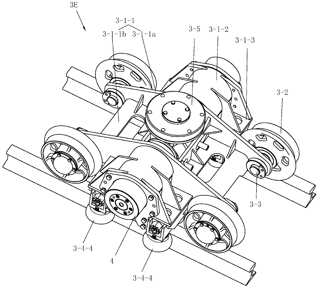
[0044] See Figure 3 to Figure 16 , the front and rear steering devices each have a steering support frame 3-1, and the steering support frame 3-1 has a walking wheel support 3-1-1 of a frame structure, which is respectively arranged on the left and right sides of the walking wheel support 3-1-1 One brake seat 3-1-2 and one rail support 3-1-3 respectively arranged on the front and rear sides of the two brake seats 3-1-2. The walking wheel support 3-1-1 is fixed by two side plates 3-1-1a and two L-shaped support frames 3-1-1b between the two side plates 3-1-1a, wherein the L-shaped support frames The bottom of 3-1-1b is bent downward to increase the strength of ...

Embodiment 2

[0070] Or be provided with at least one mechanical speed taking device 9 on the rear steering device 3F of the head car T, or be provided with at least one mechanical speed taking device 9 on the rear steering device 3F of the tail car W, or be provided with at least one speed taking device 9 between the head car T and the tail car Each rear steering device 3F of W is provided with at least one mechanical speed taking device 9 . In this implementation, the rear steering device 3F of the rear car W is provided with two mechanical speed-taking devices 8 respectively on the left and right sides and opposite, see Figure 20 to Figure 22 , the mechanical speed taking device 9 includes a second large gear 9-1 fixed on the road wheel shaft 3-3, a second mount 9-4 fixed on the corresponding position of the road wheel bracket 3-1-1, and The second speed measuring shaft 9-3 that the second mounting seat 9-4 is dynamically connected, is fixed on the second speed measuring shaft 9-3 one e...

Embodiment 3

[0074] Or on the road wheel bracket 3-1-1 of the rear steering device 3F of the head car, an electric speed taking device 8 and a mechanical speed taking device 9 are respectively located on the left and right sides and opposite, or on the rear steering device of the tail car The traveling wheel support 3-1-1 of 3F is provided with an electric speed-taking device 8 and a mechanical speed-taking device 9 respectively on the left and right sides and facing each other. See Figure 23 , The structures of the electric speed-taking device and the mechanical speed-taking device in Embodiment 3 can refer to Embodiment 1 and Embodiment 2, respectively. See Figure 24 , compared with the hydraulic system of embodiment 1, the hydraulic system of embodiment 3 differs in that the hydraulic system of embodiment 3 has a second cut-off reversing valve W11, and the second cut-off reversing valve W11 is the same as the first cut-off reversing valve T9 is connected in parallel, the first cut-o...


PUM


Abstract

The invention discloses an inclined shaft common rail clamping rail man car. The inclined shaft common rail clamping rail man car comprises a head car and a tail car, each of the head car and the tailcar comprises a front steering device, a rear steering device and caliper type hydraulic brakes, the steering support frames of the front steering device and the rear steering device are provided with walking wheel supports with frame structures, brake seats fixed on the left side and the right side of the walking wheel supports correspondingly and clamping rail supports correspondingly fixed onthe front side and the rear side of the brake seats; the four clamping rail supports are correspondingly connected with a group of clamping rail devices, and steering assemblies are correspondingly fixed on the steering support frames of the front steering device and the rear steering device; and the four caliper type hydraulic brakes are correspondingly fixed in the four brake seats, and the control system controls the braking linkage. According to the inclined shaft common rail clamping rail man car, the front steering device and the rear steering device are modularized, the walking, the multi-direction steering, the caliper type braking and the floating type clamping rail are integrated, the structure is compact, the safety performance is reliable, and convenience is provided for vehicle assembly. The head car and the tail car are both man cars and have the braking function, a man car can be connected between the head car and the tail car, and a special brake car does not need to bespecially arranged.

Description

technical field [0001] The invention relates to a common rail card rail passenger car for inclined shafts used in coal mines. Background technique [0002] In coal mine roadway, the safe transportation of personnel is an important issue. The patent literature of China Authorized Announcement No. CN101407222B discloses a undulating roadway passenger car for coal mines, which has a brake car and a passenger car. The meeting at both ends, the passenger car includes a vehicle frame, a compartment, No. 1 steering support frame and No. 2 steering support frame arranged at the bottom of the vehicle frame, and the meeting at two ends of the vehicle frame. The brakes mentioned above are caliper brakes. The man-cart is mainly used for the transportation of personnel in underground troughs and panels of coal mines, and requires a special brake car. At present, in the transportation of personnel in the inclined shaft roadway, the more common transportation method is that the hoist dr...

Claims


Application Information

Patent Timeline
IPC IPC(8): B61D15/00B61F5/00B61F5/16B61H11/06B61H11/02B61F5/50
CPCB61D15/00B61F5/00B61F5/16B61H11/06B61H11/02B61F5/50
Inventor 王眉林史发慧雷鹏刘国芳钱军黄建伟
Owner CHANGZHOU DEV & MFR CENT
Why Eureka
Try Eureka