Cooling water emergency water supply system and method

A water supply system and cooling water technology, which is applied to water supply pipeline systems, water supply devices, water supply devices, etc., can solve the problems of high investment and renovation operation and maintenance costs, difficulty in maintaining water quality, and poor construction flexibility, so as to save investment and construction costs, Increased flexibility, adaptable results

Pending Publication Date: 2019-11-08
S Y TECH ENG & CONSTR CO LTD
View PDF0 Cites 3 Cited by
  • Summary
  • Abstract
  • Description
  • Claims
  • Application Information

AI Technical Summary

Problems solved by technology

[0004] Aiming at the above-mentioned defects of the prior art, the present invention provides an emergency water supply system for cooling water, which solves the problems of poor construction flexibility, low system adaptability, difficulty in maintaining water quality, and high investment, transformation, operation and maintenance costs in the traditional emergency water supply scheme.

Method used


Image

  • Cooling water emergency water supply system and method
  • Cooling water emergency water supply system and method

Examples


Embodiment 1

[0028] Embodiment 1 Cooling water emergency water supply system (1)

[0029] 1. Structure of cooling water emergency water supply system

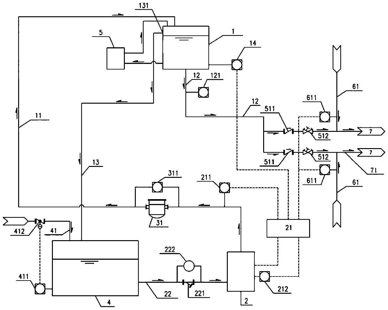
[0030] Such as figure 1 As shown, the cooling water emergency water supply system includes a high-level transfer water tank 1, an engine control panel 21, a water supply pump 2, a low-level water storage tank 4 and a water supply pipeline.

[0031] The elevation of the high-level transfer water tank 1 meets the water pressure required by emergency water supply users, and the volume of the high-level transfer water tank 1 meets the emergency water consumption for storing 1 minute. The water outlet of the high-level transfer water tank 1 is connected with the water outlet pipe 12 of the high-level water tank. The high water tank outlet pipe 12 and the conventional circulating cooling water supply pipe 61 are respectively connected to the user water inlet pipe 71, and the user water inlet pipe 71 supplies water to the user. A check valve 51...

Embodiment 2

[0048] Embodiment 2 Cooling water emergency water supply system (2)

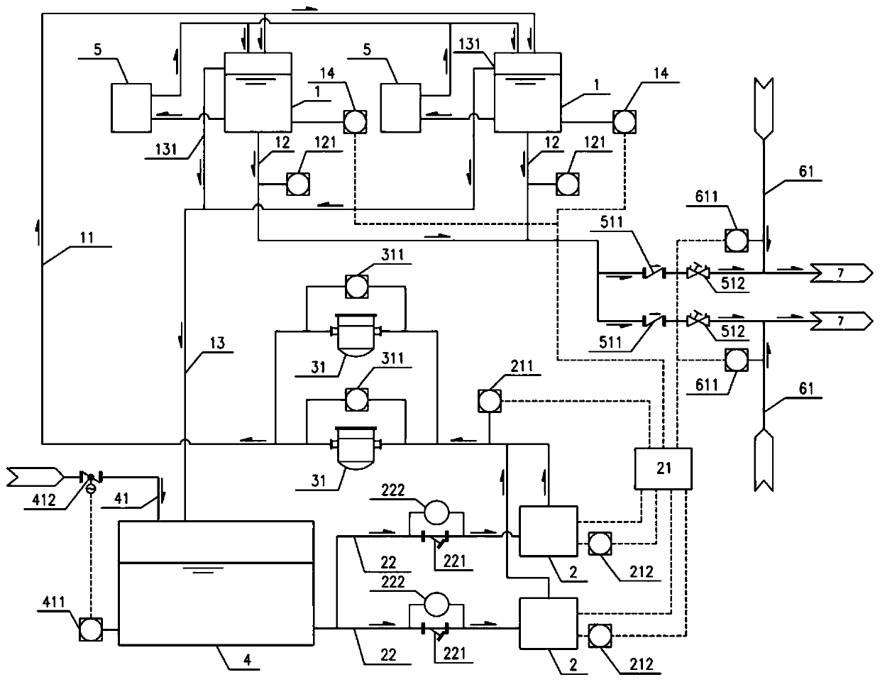
[0049] In order to ensure the reliability of emergency cooling water supply and facilitate equipment maintenance, there can be two or more devices in the emergency cooling water supply system. Such as figure 2 As shown, there are two sets of high-level transfer water tank 1, water supply pump 2, filter 31 and their supporting equipment in the cooling water emergency water supply system. The two sets of the same devices are connected in parallel. When using, you can choose a single set of operation or two sets of equipment run concurrently.


PUM


Abstract

The invention provides a cooling water emergency water supply system and method. The system comprises a high-position transfer water tank, an engine control panel, a water supply pump, a low-positionwater storage pool and a water supply pipeline. The elevation of the high-position transfer water tank meets the water pressure required by the emergency water supply to a user. The size of the high-position transfer water tank meets the requirement for at least storing 1 minute of emergency water consumption. A high-position water tank water outlet pipe and a conventional circulating cooling water supply pipe are connected with a user water inlet pipe. The user water inlet pipe supplies water to the user. A check valve is arranged on the high-position water tank water outlet pipe. A pressuresensor is arranged on the conventional circulating cooling water supply pipe. The pressure sensor is connected with the engine control panel through a circuit. The engine control panel is connected with a water supply pump through a circuit. A water outlet of the low-position water storage pool is connected with a water inlet of the water supply pump. A water outlet of the water supply pump is connected with a water inlet of the high-position transfer water tank. The system is safe, stable and convenient to maintain; and the volume of the high-position transfer water tank is small, the volumeof a supporting system of the high-position transfer water tank is smaller, and therefore flexibility of construction is greatly improved.

Description

technical field [0001] The invention belongs to the technical field of emergency water supply, in particular to an emergency water supply system for cooling circulating water. Background technique [0002] The emergency water supply system is widely used in glass firing, silicon rod drawing, nuclear energy utilization and other fields. In the process of process production, some process equipment (such as furnaces) need a steady stream of cooling water to ensure the safe operation of the equipment. Once the flow is cut off, the equipment may be damaged, and even cause serious secondary disasters such as fire. However, due to objective factors, construction costs, and system configuration limitations, it is difficult to ensure cooling water supply in the event of power outages, equipment failures, etc. For process equipment with high water supply safety requirements, it is often necessary to be equipped with an emergency water supply system as a supplement and backup to the c...

Claims


Application Information

Patent Timeline
Patent Type & Authority Applications(China)
IPC IPC(8): E03B1/04E03B11/00E03B11/16E03B11/12E03B7/07
CPCE03B1/04E03B7/07E03B7/075E03B11/00E03B11/12
Inventor 刘其杰李锦生王鹏周瑾姚成才
Owner S Y TECH ENG & CONSTR CO LTD
Why Eureka
Try Eureka