Ceramic sintering device and ceramic sintering method

A sintering device and ceramic technology, applied in the direction of electric furnace heating, furnace type, furnace, etc., can solve the problems that are difficult to meet, pollute the sample surface, etc., and achieve the effect of easy operation, simple process flow, and lower temperature

Inactive Publication Date: 2019-11-08
SHENZHEN GRADUATE SCHOOL TSINGHUA UNIV
View PDF2 Cites 5 Cited by
  • Summary
  • Abstract
  • Description
  • Claims
  • Application Information

AI Technical Summary

Problems solved by technology

[0004] However, the flash firing technology still has some limitations: conductive electrodes need to be coated on both sides of the ceramic green body, which pollutes the surface of the sample, and the conductive electrodes must be ground off after the sintering is completed; the shape of the ceramic green body is mostly dog Bone-shaped and disc-shaped, it is difficult to meet the requirements for ceramic shapes in different applications; devices that require additional heating, such as tube furnaces, muffle furnaces, etc.

Method used


Image

  • Ceramic sintering device and ceramic sintering method
  • Ceramic sintering device and ceramic sintering method
  • Ceramic sintering device and ceramic sintering method

Examples


preparation example Construction

[0050] see Figure 4 , the embodiment of the present invention also provides a preparation method for realizing ceramic sintering by using the ceramic sintering device 100, comprising the following steps:

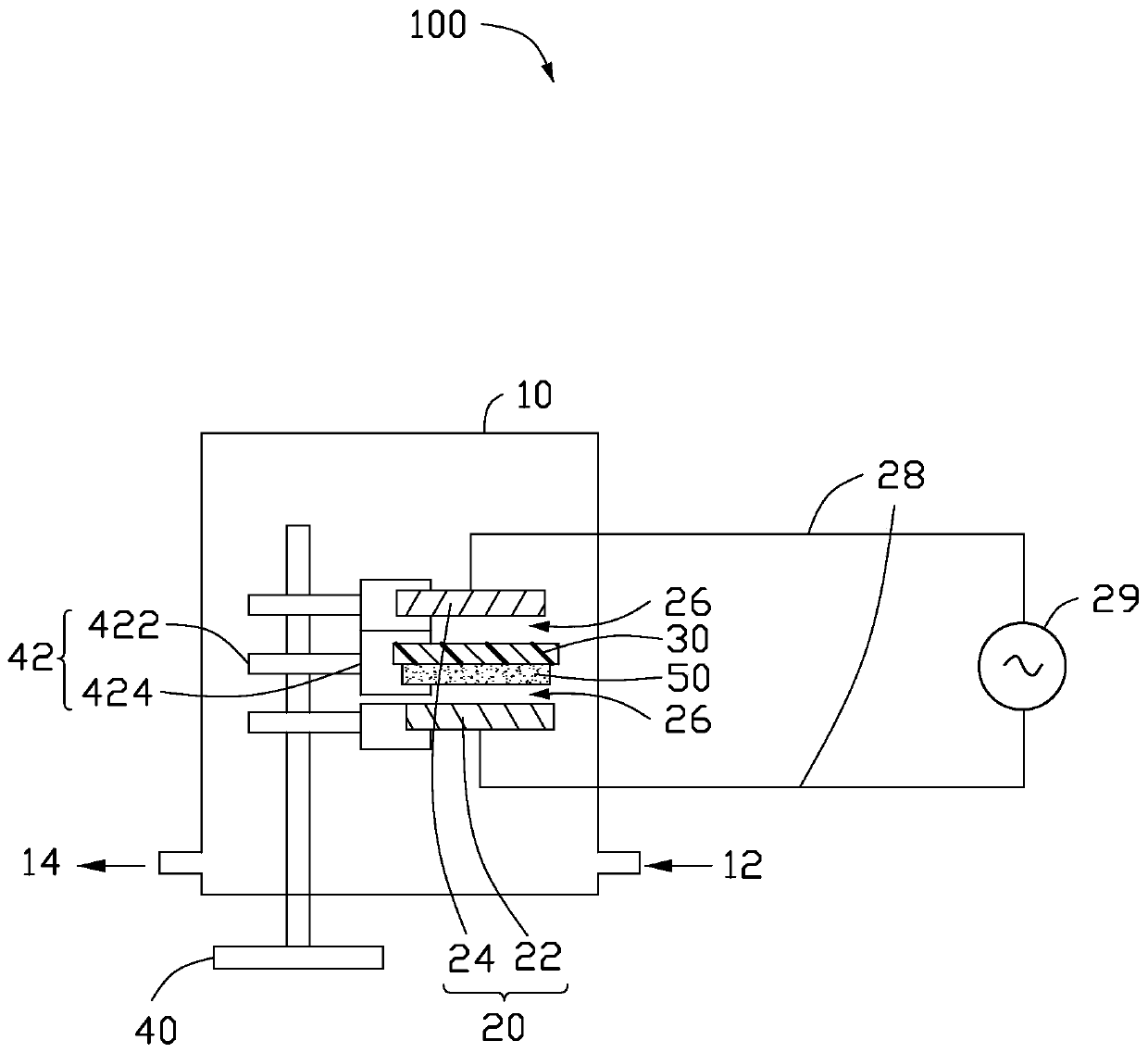
[0051] Step S1: fixing a ceramic green body 50 in the ceramic sintering device 100, the ceramic green body 50 has the same shape as the barrier medium 30 and the electrode 20, and the ceramic green body 50 and the electrode There is an air gap 26 between 20;

[0052] Step S2: passing a specific gas into the ceramic sintering device 100, so that the ceramic green body 50 is placed in the gas;

[0053] Step S3: Turn on the power supply 29, increase the amplitude of the output voltage of the power supply 29, excite the gas in the air gap 26 to generate discharge, and cut off the power supply 29 after maintaining for a certain period of time to obtain ceramics sintered by gas discharge.

Embodiment 1

[0064] A disc-shaped zinc oxide ceramic green body 50 is fixed on figure 1 On the support in the ceramic sintering device 100 shown, wherein, the thickness of the ceramic green body 50 is 1 mm, and the diameter is 10 mm; the first electrode 22 and the second electrode 24 in the ceramic sintering device 100 are circular plates of the same size, The diameter of the electrode 20 is 10 mm; the blocking medium 30 is a square aluminum oxide ceramic sheet, the thickness of the blocking medium 30 is 1 mm, and the side length is 50 mm. The ceramic green body 50 and the barrier medium 30 are tightly bonded without leaving an air gap 26, and an air gap 26 with a thickness of 0.5 mm is left between the barrier medium 30 and the first electrode 22, and the ceramic green body 50 and the second electrode 24 leaving an air gap 26 with a thickness of 0.5 mm. Adopt the AC power supply 29, connect the power supply 29, set the frequency of the voltage to 5kHz, gradually increase the amplitude of...

Embodiment 2

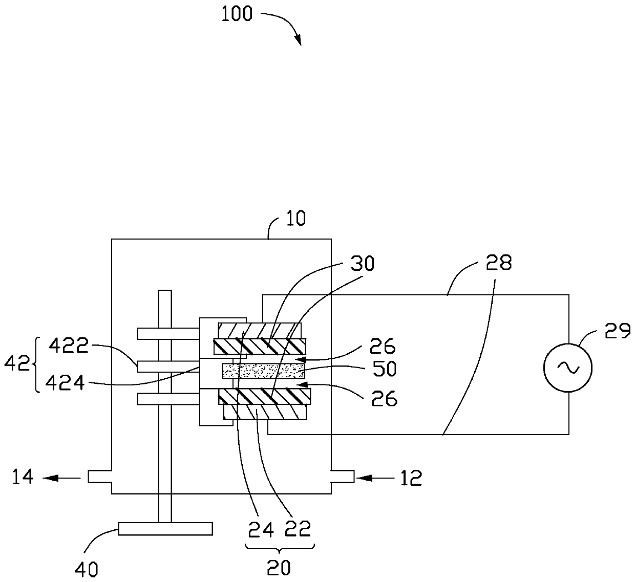
[0066] The difference from Embodiment 1 is that the barrier medium 30 is closely attached to the first electrode 22 and the second electrode 24 without leaving an air gap 26, and the gap between the ceramic green body 50 and the barrier medium 30 is respectively An air gap 26 with a thickness of 0.5 mm is provided. The power supply 29 is a nanosecond pulse power supply, the frequency of the voltage is set to 1kHz, and the pulse width is set to 50ns.

[0067] Others are the same as in Embodiment 1, and will not be repeated here.


PUM

PropertyMeasurementUnit
thicknessaaaaaaaaaa
lengthaaaaaaaaaa
lengthaaaaaaaaaa

Abstract

A ceramic sintering device is used for sintering a ceramic raw blank and comprises a box, an electrode, a stop medium and a fixing support. The electrode and the stop medium are arranged in the box through the fixing support. The electrode comprises a first electrode body and a second electrode body which are arranged in a spaced manner. The stop medium is arranged between the first electrode bodyand the second electrode body and is spaced from the first electrode body and / or the second electrode body. The fixing support is further used for fixing the ceramic raw blank between the first electrode body and the second electrode body, and the ceramic raw blank and the stop medium are arranged in an interval or spaced manner. The invention further provides a ceramic sintering method of the ceramic sintering device.

Description

technical field [0001] The invention relates to the technical field of ceramic material preparation, in particular to a ceramic sintering device and a ceramic sintering method. Background technique [0002] Ceramic materials are widely used in various fields, for example, they can be used to manufacture solar cells, piezoelectric devices and so on. The formation of ceramic materials requires the ceramic powder to be turned into a green body through molding technology, and the ceramic green body is then sintered to make the crystal grains migrate and grow, and the green body shrinks to form a ceramic material. Using the conventional high-temperature sintering method, the general sintering temperature of ceramics is above 1000°C, which requires high energy consumption and cost for ceramic sintering. In recent years, many new ceramic sintering technologies have been discovered, such as discharge plasma sintering, microwave sintering, flash firing, cold firing, etc. [0003] A...

Claims


Application Information

Patent Timeline
Patent Type & Authority Applications(China)
IPC IPC(8): F27B17/00F27D11/10
CPCF27B17/00F27D11/10
Inventor 王希林刘杰明张若兵贾志东
Owner SHENZHEN GRADUATE SCHOOL TSINGHUA UNIV
Why Eureka
Try Eureka