Method for controlling outlet temperature of cooling liquid of electronic equipment

A technology for cooling liquid outlet and control electronics, which is applied to structural parts of electrical equipment, cooling/ventilation/heating renovation, electrical components, etc., which can solve the complexity of liquid cooling control system, realize low cost, and break the upper limit of cooling liquid outlet temperature and other problems, to achieve the effect of high reliability, lower system cost, and lower complexity.

Active Publication Date: 2020-07-21
10TH RES INST OF CETC
View PDF13 Cites 0 Cited by
  • Summary
  • Abstract
  • Description
  • Claims
  • Application Information

AI Technical Summary

Problems solved by technology

[0005] The purpose of the present invention is to aim at the deficiencies of the existing technology, and provide a method that can reduce the complexity of the liquid cooling control system, achieve low cost, high reliability, and control the outlet temperature of the cooling liquid of electronic equipment, so as to solve the problem of electronic equipment cooling. Thermal control problem when the coolant outlet temperature breaks through the upper limit when the equipment is in transient operation

Method used


Image

  • Method for controlling outlet temperature of cooling liquid of electronic equipment
  • Method for controlling outlet temperature of cooling liquid of electronic equipment
  • Method for controlling outlet temperature of cooling liquid of electronic equipment

Examples


Embodiment 1

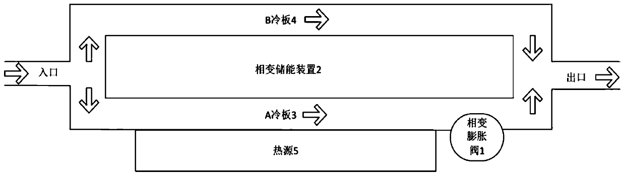
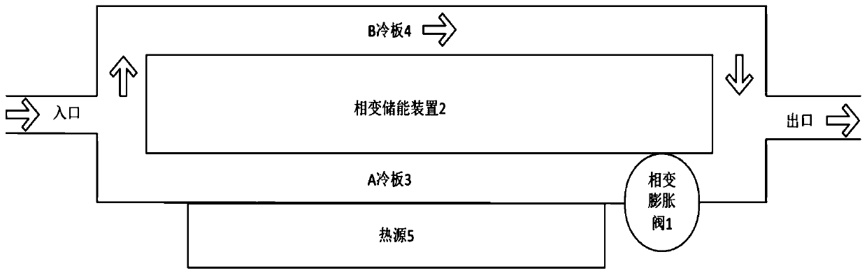
[0023] When the heat source is loaded under typical low heat consumption conditions, the flow channels of cold plate A and cold plate B are connected at the same time, and the phase change energy storage device and the phase change expansion valve are not working. After the coolant enters the liquid cooling system from the inlet, it flows through the The cold plate runner is heated by the heat source and discharged from the outlet of the runner. At this time, because it is a low heat consumption condition, the outlet temperature does not exceed the allowable value.

Embodiment 2

[0025] Load the heat source under typical high heat consumption conditions. The phase change expansion valve located downstream of the flow channel of the cold plate A undergoes a phase change when heated, and the volume expands significantly to block the flow channel of the cold plate A, shut off the flow channel of the cold plate A, and all the cooling liquid flows from the cold plate B Runner through. The heat first passes through the phase change energy storage device before reaching the B cold plate as the final heat sink. During this process, the phase change energy storage device absorbs heat and undergoes a phase change at its phase change point, and the phase change material in it becomes liquid , and release a heat consumption lower than the total heat consumption of the heat source at the contact surface with the B cold plate. Therefore, the coolant flowing through the channel of the cold plate B only needs to absorb a relatively low amount of heat per unit time, s...

Embodiment 3

[0027] Load the heat source again with typical low heat consumption conditions. At this time, the heat release rate of the phase change energy storage device is greater than its heat absorption rate, and the phase change material in it undergoes a phase change again to return to a solid state; at the same time, the phase change expansion valve also undergoes a phase change again, and the volume shrinks, thereby opening A The flow channel of the cold plate makes the liquid cooling system return to its original state.

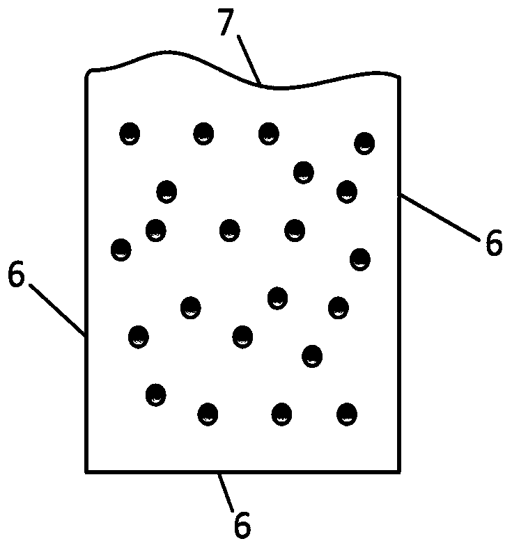
[0028] In an optional embodiment, the phase change material is packed into a box made of aluminum alloy 6 except for the top surface, the top surface of the box is made of flexible material 7, and the box is packaged to form a phase change expansion valve 1 . The phase change material is packaged into the metal cavity to form the phase change energy storage device 2 .

[0029] The phase change energy storage device 2 is connected with the cold plate A 3 and the...


PUM


Abstract

The invention discloses a method for controlling the temperature of the coolant outlet of an electronic device. The method can solve the problem that the temperature of the coolant outlet exceeds theupper limit when the electronic device is in transient operation. The method comprises the following steps of: selecting a phase change material having a phase change point between the highest workingambient temperature and the allowable temperature of a key component in the electronic device; packaging the selected phase change material in a phase change expansion valve having one side preparedfrom a flexible heat conduction material; packaging the selected phase change material in a metal plate to form a phase change energy storage device; constructing a liquid cooling system having an A cold plate, a B cold plate, the phase change energy storage device, the phase change expansion valve and diverting and converging pipelines; placing the phase change expansion valve downstream of an Acold plate flow channel; controlling the upper limit of the temperature of the coolant outlet when the electronic device is in transient operation by the synergistic effect of the valve effect and theenergy storage and discharge effect of the phase change device; if the heat sink A cold plate flow channel for heat transfer is cut off, the phase change energy storage device transfers the heat instead in order to supply the heat to the heat sink B cold plate.

Description

technical field [0001] The invention relates to the field of thermal control of electronic equipment, and relates to a method for controlling the outlet temperature of cooling liquid of electronic equipment. Background technique [0002] The thermal control of electronic equipment is to ensure the normal operation of electronic equipment and its components and devices within the specified temperature range, such as cooling, heating or constant temperature measures, using heat conduction, convective heat transfer or radiation heat transfer to dissipate the components and devices The heat is dissipated to the surrounding environment. The cooling methods commonly used in modern electronic equipment are: natural cooling, forced ventilation cooling, liquid cooling, evaporative cooling, soda-water two-phase flow cooling, semiconductor refrigeration, heat pipe cooling, etc. The choice of cooling method mainly depends on the surface heating power density of the component, device or...

Claims


Application Information

Patent Timeline
Patent Type & Authority Patents(China)
IPC IPC(8): H05K7/20
CPCH05K7/20327H05K7/20381
Inventor 翁夏
Owner 10TH RES INST OF CETC
Why Eureka
Try Eureka