Zoom lens

A zoom lens and lens technology, applied in the field of zoom lenses, can solve the problems of not very high resolution, lens volume changes, and difficult control of monitoring distance, etc., to achieve the effect of improving lens effect, high photosensitive performance, and adjusting sharpness

Pending Publication Date: 2019-11-12
UNION OPTECH
View PDF0 Cites 1 Cited by
  • Summary
  • Abstract
  • Description
  • Claims
  • Application Information

AI Technical Summary

Problems solved by technology

[0003] Ordinary zoom lenses are often unable to be compatible with large image area and volume. The increase of image area will also cause a sharp change in lens volume. Currently, large-screen surveillance lenses on the market, such as lenses with a chip size of about 1.7″, have an image area of ​​up to 9.5mm, mostly fixed-focus lenses, difficult to control when the monitoring distance changes, and the length is longer, usually greater than 70mm;
[0004] The resolution is low. Most of the mainstream high-quality surveillance cameras currently on the market have a resolution of 1080p and a pixel count of 2 million. Pixels can no longer meet the needs
The current mainstream 1080P lens image plane is mainly 1 / 2.8″, using a 1 / 2.8″ CMOS chip with an effective imaging plane diagonal of 6.2mm, its pixel size is only 2.8μm, and the resolution is not very high
Moreover, due to the small pixels, its photosensitivity and color reproduction performance are not very ideal, and performance improvement is urgently needed;
[0005] At present, the surveillance lenses on the market basically have large optical distortion changes under different focal lengths, which is not conducive to the application in artificial intelligence related fields such as face recognition and license plate recognition that are gradually becoming popular;
[0006] The surveillance lenses currently on the market are basically non-infrared confocal lenses. Therefore, in occasions with many optical wavelength bands, such as in the evening, or when there is some lighting at night, the captured picture cannot be clear as a whole, and there will always be some blur

Method used


Image

  • Zoom lens
  • Zoom lens
  • Zoom lens

Examples


Embodiment Construction

[0029] The present invention will be further described below in conjunction with accompanying drawing:

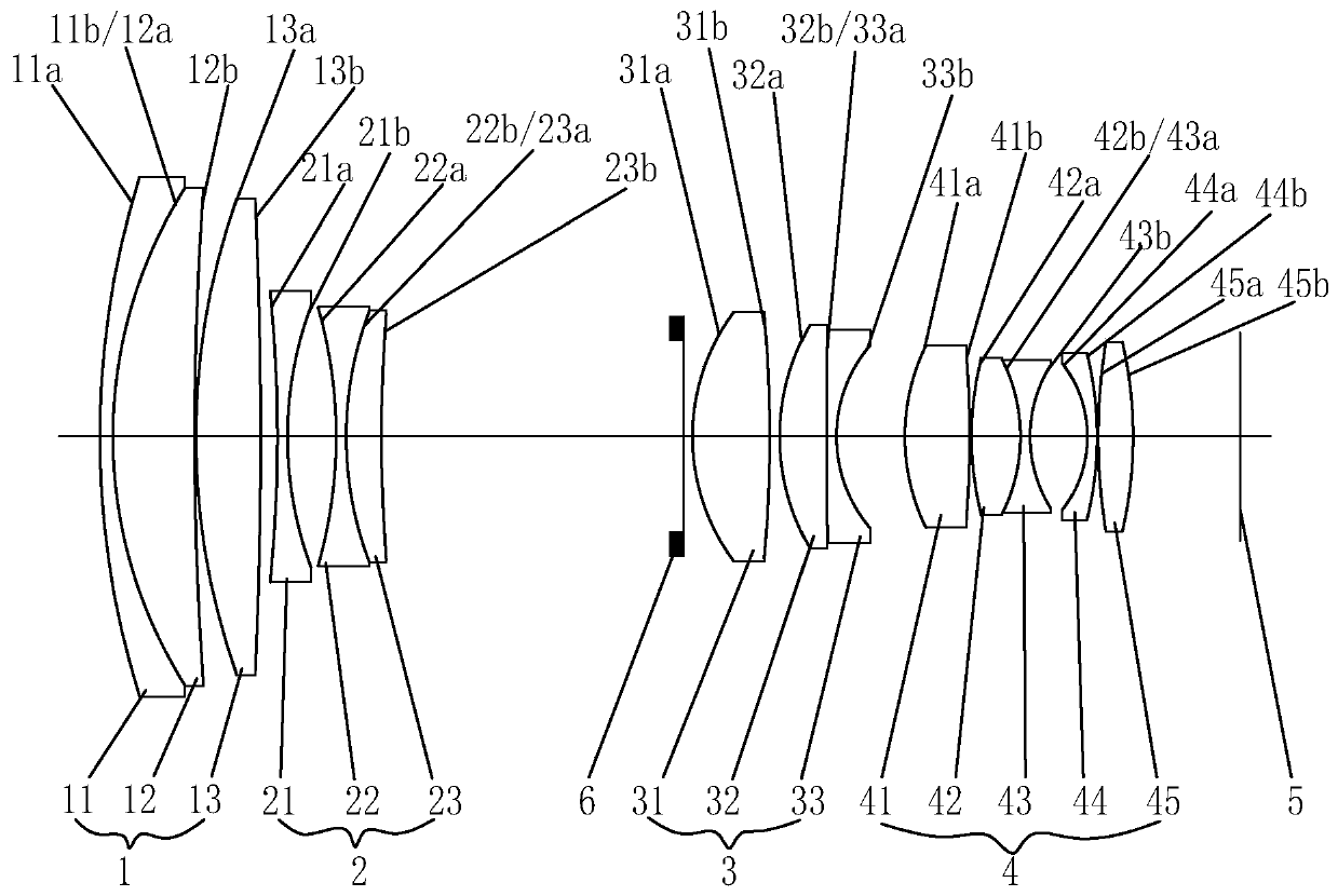
[0030] Such as figure 1 As shown, a zoom lens includes a photosensitive chip 5 that can convert light into electrical signals, and one side of the photosensitive chip 5 is provided with a first lens group 1 and a third lens group 3 that can be fixed relative to the photosensitive chip 5 , the third lens group 3 is arranged between the first lens group 1 and the photosensitive chip 5, and the fourth lens group that can move relative to the photosensitive chip 5 is arranged between the third lens group 3 and the photosensitive chip 5 4. A second lens group 2 that can move relative to the photosensitive chip 5 is provided between the first lens group 1 and the third lens group 3. The second lens group 2 is used when the lens changes from a short focal length to a long focal length. In the process of changing, it gradually moves closer to the third lens group 3, and a diaphrag...


PUM


Abstract

The invention discloses a zoom lens. The zoom lens comprises a photosensitive chip, and one side of the photosensitive chip is provided with a first lens group and a third lens group which can be fixed relative to the photosensitive chip; the third lens group is disposed between the first lens group and the photosensitive chip; a fourth lens group movable relative to the photosensitive chip is arranged between the third lens group and the photosensitive chip; a second lens group is disposed between the first lens group and the third lens group to gradually approach the third lens group when the lens is focused from a short focal length to a long focal length; and between the second lens group and the third lens group, an aperture capable of control the amount of light beams entering the lens is provided. The focal length of the first lens group is positive, the focal length of the second lens group is negative, the focal length of the third lens group is positive, and the focal lengthof the fourth lens group is positive. The third lens group comprises an aspheric lens surface, and the fourth lens group comprises an aspheric lens surface. The lens of the invention has high transmittance, good imaging effect, high resolution, small distortion, small volume, large image plane and infrared confocal.

Description

【Technical field】 [0001] The invention relates to a zoom lens. 【Background technique】 [0002] At present, zoom lenses are widely used in people's daily life. The current market is developing in the direction of high resolution and high image quality. In order to obtain better imaging quality, using chips with larger pixels and more pixels is the solution to the problem. One of the fundamental ways, but the current security monitoring and road condition monitoring devices have the following shortcomings: [0003] Ordinary zoom lenses are often unable to be compatible with large image area and volume. The increase of image area will also cause a sharp change in lens volume. Currently, large-screen surveillance lenses on the market, such as lenses with a chip size of about 1.7″, have an image area of ​​up to 9.5mm, mostly fixed-focus lenses, difficult to control when the monitoring distance changes, and the length is longer, usually greater than 70mm; [0004] The resolution...

Claims


Application Information

Patent Timeline
Patent Type & Authority Applications(China)
IPC IPC(8): G02B15/16G02B13/00G02B13/14G02B13/18G02B1/00
CPCG02B1/00G02B13/0045G02B13/006G02B13/008G02B13/009G02B15/16
Inventor 王东阳龚俊强王晓李建华
Owner UNION OPTECH
Why Eureka
Try Eureka