
Control method, control system and exit actuating mechanism control method for hanging assembly line

A control method and technology of actuators, which are applied in general control systems, control/regulation systems, program control, etc., can solve the problems of complex control system structure, high installation accuracy requirements, slow data transmission speed, etc., and achieve a simple system structure. , The distribution location requirements are not high, and the data transmission speed is fast.

Active Publication Date: 2019-11-12
NINGBO SUNRISE IND AUTOMATION CO LTD +1
View PDF10 Cites 9 Cited by
  • Summary
  • Abstract
  • Description
  • Claims
  • Application Information

AI Technical Summary

Problems solved by technology

[0008] The structure of the control system is complex, requiring two RFID card readers and an inductive proximity switch at each workstation, as well as an RFID card reader for detecting gaps. distribution, so that the RFID card reader used to detect the gap can accurately read the RFID information on each gap, and the system judges whether there is a hanger on the gap by the inductive proximity switch of each workstation. The installation position of each gap on the main rail and the distance between the RFID card reader for detecting the gap and the inductive proximity switch of each workstation require high installation accuracy; on the other hand, the terminal equipment and the host computer use CAN bus communication, Slow data transmission speed; using serial communication, when the host computer accesses a large number of workstations, it is easy to cause data congestion
The structure of the control system is complex, and the terminal equipment and the upper computer use CAN bus communication, and the data transmission speed is slow; when the serial communication is used, when the number of workstations connected to the upper computer is large, it is easy to cause data congestion

Method used


Image

  • Control method, control system and exit actuating mechanism control method for hanging assembly line
  • Control method, control system and exit actuating mechanism control method for hanging assembly line
  • Control method, control system and exit actuating mechanism control method for hanging assembly line

Examples


Embodiment Construction

[0045] The present invention will be further described below in conjunction with specific embodiments.

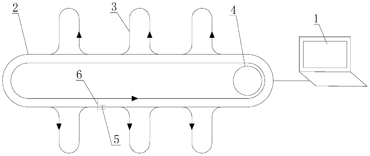
[0046] like figure 1 As shown, the hanging assembly line control system of the present invention mainly includes a main computer 1, a main rail 2, at least two or more workstations 3, a driving mechanism 4, and a clothes hanger 5 is hung on the main rail 2. The workstations 3 are distributed on the outside of the main rail 2, and the top of the main rail 2 is provided with push rods 6 distributed at a certain interval. The push rods 6 are driven by the driving mechanism 4 to push the clothes hangers 5 on the main rail 2 to run in a specified direction. RFID chips are all installed on the push rod 6 and the clothes hanger 5 .

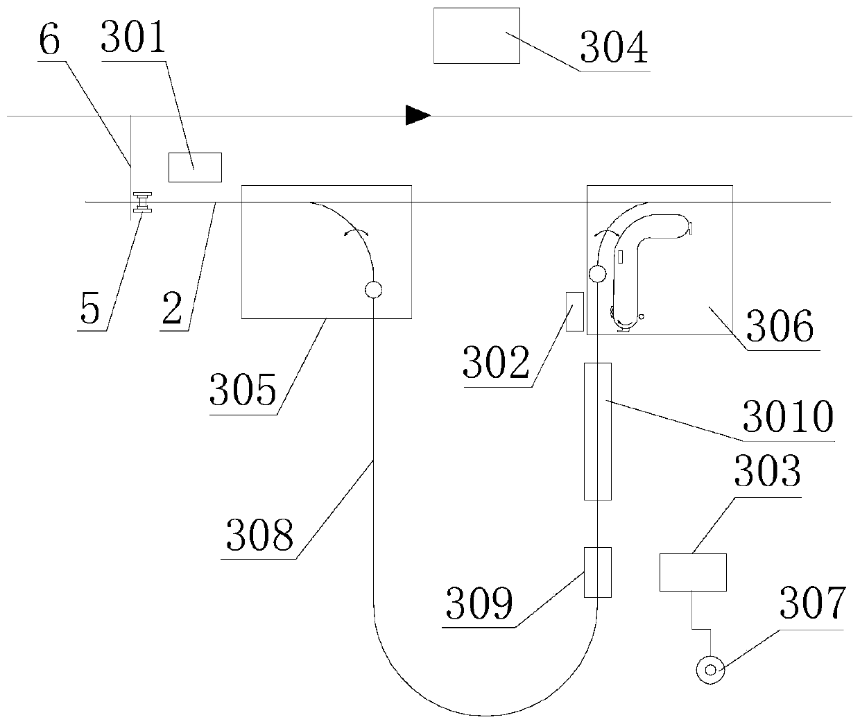
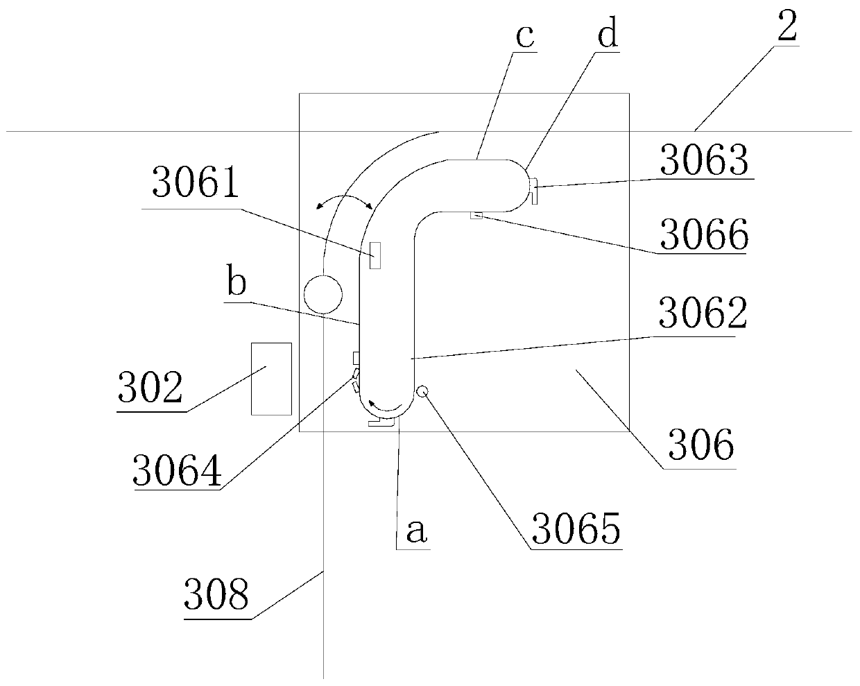
[0047] like figure 2 As shown, the workstation 3 includes an inbound card reader 301, an outbound card reader 302, a touch panel 303, a communication data controller 304, an inbound actuator 305, an outbound actuator 306, a lift button 307, and a r...


PUM


Abstract

The invention discloses an exit control method for a hanging assembly line. The exit control method comprises the following steps: when clothes hanger information is read by an exit card reader, sending a signal to a main computer, and judging whether a push rod going through an entrance card reader currently is empty or not by the main computer; if the push rod is empty, controlling an exit actuating mechanism to drive a clothes hanger to exit by the main computer or through a communication data controller, pushing the clothes hanger after exiting to move on a main rail by the push rod, and enabling the push rod number of the push rod to be associated with the clothes hanger number of the clothes hanger by the main computer; or, enabling the clothes hanger not to exit; and after the clothes hanger exits completely, stopping operation of the exit actuating mechanism. Moreover, the invention provides a control system and an exit actuating mechanism control method for the hanging assembly line, and two clothes hangers are avoided from appearing on the same push rod.

Description

technical field [0001] The invention belongs to the technical field of hanging conveyor lines, and more specifically, relates to a hanging assembly line control method, system, and outbound actuator control method. Background technique [0002] In recent years, the emergence of hanging assembly lines for clothing and home textiles has completely changed the traditional production mode, realized automatic control of the processing process, improved production efficiency, and facilitated production management. [0003] On the one hand, the current hanging assembly line is more complicated in the control method of the hangers entering and exiting the station. [0004] On the other hand, the hanging assembly line originally used RS485 communication technology, but now it generally uses CAN bus to communicate with the host computer. This communication mode has the disadvantages of relatively low communication distance, communication rate and bandwidth, and cannot meet the commun...

Claims


Application Information

Patent Timeline
Patent Type & Authority Applications(China)
IPC IPC(8): G05B19/418B65G43/00G06K17/00
CPCG05B19/41865B65G43/00G06K17/00G05B2219/32252B65G2201/0229Y02P90/02
Inventor 孙建国余云林袁峰袁剑
Owner NINGBO SUNRISE IND AUTOMATION CO LTD
Learn More