Data transmission method and system between memory database system and data warehouse system

A data transmission method and data transmission system technology, applied in the field of data processing, to achieve real-time efficient processing capabilities and comprehensive data analysis effects

Inactive Publication Date: 2019-11-12
BORRUI DATA TECH (BEIJING) CO LTD
View PDF8 Cites 4 Cited by
  • Summary
  • Abstract
  • Description
  • Claims
  • Application Information

AI Technical Summary

Problems solved by technology

[0006] The purpose of the present invention is to provide a data transmission method and system between the mem

Method used


Image

  • Data transmission method and system between memory database system and data warehouse system
  • Data transmission method and system between memory database system and data warehouse system
  • Data transmission method and system between memory database system and data warehouse system

Examples


Embodiment 1

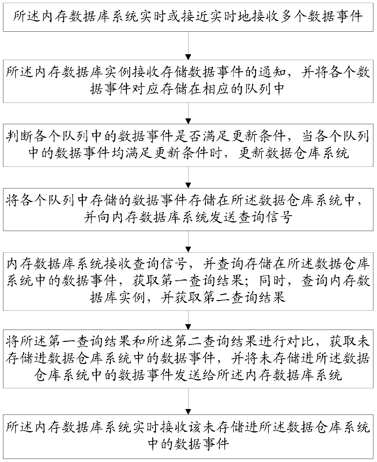
[0042] Such as Figure 1 to Figure 2As shown, this embodiment provides a method for data transmission between an in-memory database system and a data warehouse system, the in-memory database system includes multiple parallel in-memory databases, and the in-memory database system also stores multiple At least one in-memory database instance for in-memory database parallel operation, including the following steps,

[0043] S1. The in-memory database system receives multiple data events in real time or close to real time;

[0044] S2. The in-memory database instance receives a notification of a stored data event, and correspondingly stores each data event in a corresponding queue;

[0045] S3. Judging whether the data events in each queue meet the update conditions, and when the data events in each queue meet the update conditions, update the data warehouse system;

[0046] S4. Store the data events stored in each queue in the data warehouse system, and send a query signal to t...

Embodiment 2

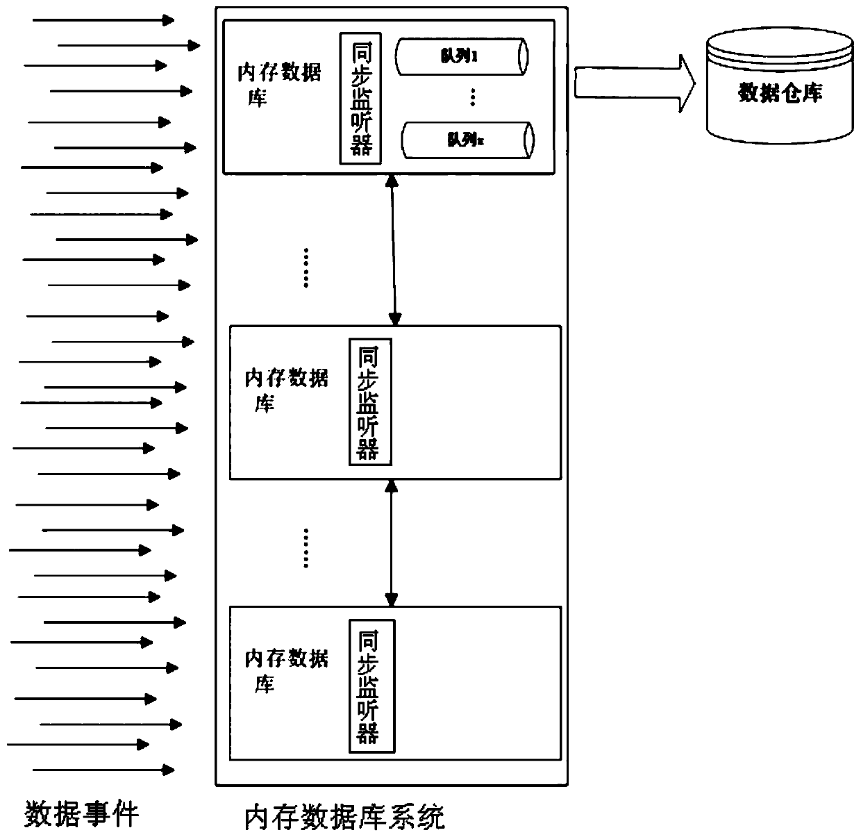
[0060] Such as image 3 As shown, in this embodiment, the in-memory database system includes multiple in-memory databases, and the in-memory databases form an in-memory database instance in parallel, and they are communicatively coupled to the data warehouse system, and the data warehouse system includes at least one data warehouse. Although each in-memory database includes a sync listener, there is only one instance of the in-memory database.

[0061] In this embodiment, although the in-memory database system receives many input data events such that any in-memory database can receive data interactions, the queuing is done by only one instance, the in-memory based database. In this implementation; all queues reside in a single in memory database. Each synchronous listener that receives a data event in its associated in-memory database can go through the process of identifying which queue received the data event and then deliver that information to the appropriate queue. As ...

Embodiment 3

[0063] Such as Figure 4 As shown, in this embodiment, the in-memory database system includes multiple in-memory database instances, which are communicatively coupled to the data warehouse system, and the data warehouse system may include at least one data warehouse. Each in-memory database includes a synchronous listener and also includes a queue; an in-memory database includes a proxy table and related micro-batch listeners. Unlike the second embodiment, the queues in this embodiment are distributed to multiple in-memory databases. An advantage of this configuration is that queues occupy resources that are separate from system resources, which can improve overall throughput. In an embodiment, network hopping is unnecessary in this architecture because the queue for each event is defined in the in-memory database where the event occurred. Each synchronous listener receives data events in its associated in-memory database and passes the received data events to the appropriate...


PUM


Abstract

The invention discloses a data transmission method and system between a memory database system and a data warehouse system. The data transmission system comprises the memory database system, the datawarehouse system, a data loading module and an SQL data management system. The data loading module is used for loading a data event into the memory database system; the memory database system sends adata event to the SQL data management system; and the SQL data management system transmits the received data event to the data warehouse system, and the data warehouse system stores the data event andsends a query signal to the memory database system so as to query the data event which is not stored in the data warehouse system. The method and system have the advantages that the limitation of a big data/rapid data system can be overcome, so that better, more comprehensive and faster data analysis can be realized.

Description

technical field [0001] The invention relates to the field of data processing, in particular to a data transmission method and system between a memory database system and a data warehouse system. Background technique [0002] As more people and businesses use computers, and as more services are delivered electronically, applications of all kinds in common use today need to receive, process and store vast amounts of data. In addition, commonly used applications also require faster response and access to more information in various analytical dimensions for making business decisions. Then there will be some problems, the shortcomings of the data processing of different systems, and when these systems interact, the negative impact of these shortcomings will be even greater, resulting in a system that is in some ways less than the sum of its parts. For example, products that implement online transaction processing (OLTP) and products that implement online analytical processing (...

Claims


Application Information

Patent Timeline
IPC IPC(8): G06F16/25G06F16/23G06F16/2455
CPCG06F16/2379G06F16/2455G06F16/25
Inventor 刘睿民
Owner BORRUI DATA TECH (BEIJING) CO LTD
Why Eureka
Try Eureka