Battery module heat conduction structure and gluing method

A battery module and heat conduction technology, applied in battery pack parts, secondary batteries, structural parts, etc., can solve the problems of difficult heat dissipation, poor heat dissipation effect, and high cell temperature, so as to facilitate heat conduction and improve the overall Robustness, the effect of reducing heat transfer paths

Inactive Publication Date: 2019-11-12
恒大新能源科技集团有限公司 +4
View PDF17 Cites 5 Cited by
  • Summary
  • Abstract
  • Description
  • Claims
  • Application Information

AI Technical Summary

Problems solved by technology

The power battery system of an electric vehicle is composed of multiple power battery cells. The power battery system generates a large amount of heat during the working process and gathers in the narrow battery box. If the heat cannot be dissipated quickly in time, high temperature It will affect the life of the power battery and even cause thermal runaway, causing fire and explosion, etc.
[0003] At present, the heat conduction of the single cell is mainly through the heat conduction aluminum plate, the heat conduction pad, and the shell. The heat dissipation effect of this structure is very poor, and the heat is difficult to export, which often causes the temperature of the cell to be too high.

Method used


Image

  • Battery module heat conduction structure and gluing method
  • Battery module heat conduction structure and gluing method
  • Battery module heat conduction structure and gluing method

Examples


Embodiment 1

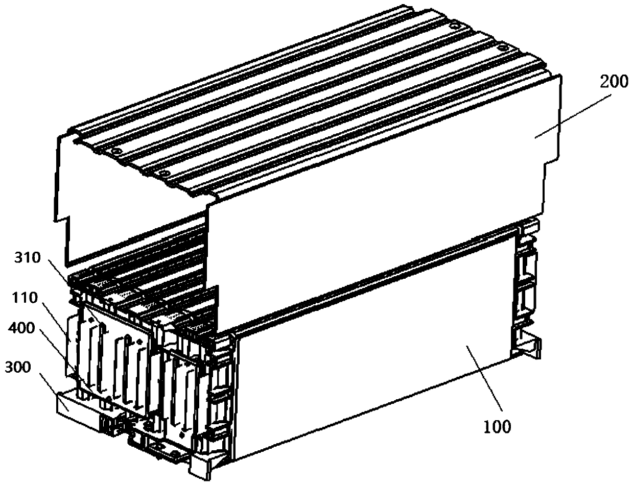
[0040] see figure 1 , before the cell assembly 100 is inserted into the U-shaped shell 200, the cell assembly is turned over 180 degrees, and the top of the cell assembly 100 after turning over is coated with thermally conductive glue, so that the filling condition of the thermally conductive glue can be visually observed, and after the thermally conductive glue is applied , and then turn the U-shaped shell 180 degrees, and then place the U-shaped shell on the top of the cell assembly, pull the U-shaped shell 200 to a certain extent with an external force, and push the cell assembly 100 into the U-shaped shell 200 with an external force , the protruding part of the U-shaped shell 200 is in contact with the glued area first, and the excess glue and air are discharged outwards to ensure the heat conduction between the battery cell assembly 100 and the U-shaped shell 200. After the thermally conductive glue is cured, the battery cell assembly 100 Can be firmly fixed in the design...

Embodiment 2

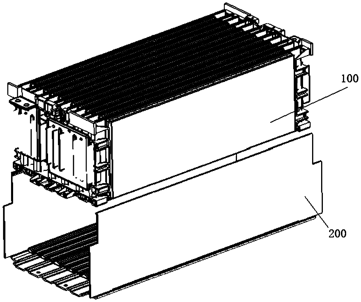
[0042] see figure 2 , put the U-shaped shell 200 in the glue coating station, use a glue applicator to coat the bottom of the U-shaped shell 200 with a certain thickness of heat-conducting glue, and then use external force to pull the U-shaped shell 200 to a certain extent, and push the cell assembly 100 to the U-shaped In the shell 200, the battery cell assembly 100 and the U-shaped shell 200 are fully squeezed, one end of the battery cell assembly 100 first contacts the glue coating area, and then the other side is contacted and pressed, and the heat-conducting glue is filled to the U-shaped area under the action of extrusion force. In the gap between the U-shaped shells 200, after the thermally conductive adhesive is cured, the U-shaped shell 200 is firmly fixed at a designated position.

[0043] The above gluing method can be determined according to actual needs. If the folded edge of the battery cell is close to the body of the battery cell, embodiment 1 or embodiment 2 ...


PUM


Abstract

The invention discloses a battery module heat conduction structure and gluing method. The battery module heat conduction structure comprises a cell component and a U-shaped shell, wherein the cell component is accommodated in the U-shaped shell; heat-conducting glue is filled into a gap between the cell component and the U-shaped shell. The gluing method comprises the step of coating glue on the cell component or the U-shaped shell before the cell component is inserted into the U-shaped shell. According to the structure and method, the heat-conducting aluminum plate is cancelled, the heat conducting path is composed of the heat-conducting glue and the aluminum shell; the heat conducting path is reduced; and compared with traditional schemes, the structure is more conductive to heat conduction of the cell, and is effectively reduced in cell temperature.

Description

technical field [0001] The invention relates to a battery module, in particular to a heat conduction structure and a glue coating method of the battery module. Background technique [0002] With the development of new energy vehicle technology, safety has been paid more and more attention. The power battery system is generally composed of battery modules, battery management system BMS, thermal management system, and some electrical and mechanical systems. Under different driving conditions of the vehicle, due to its own internal resistance, the single battery cell will generate a certain amount of heat while outputting electric energy, making its own temperature higher. When its own temperature exceeds its normal operating temperature range, it will Affect battery performance and life. The power battery system of an electric vehicle is composed of multiple power battery cells. The power battery system generates a large amount of heat during the working process and gathers ...

Claims


Application Information

Patent Timeline
Patent Type & Authority Applications(China)
IPC IPC(8): H01M2/10H01M10/613H01M10/625H01M10/653H01M10/655
CPCH01M10/613H01M10/625H01M10/653H01M10/655H01M50/20Y02E60/10
Inventor 张芳吴斌凡朋杨政杰杜禾何标
Owner 恒大新能源科技集团有限公司
Why Eureka
Try Eureka