Antenna matching circuit

An antenna matching and matching circuit technology, which is applied to circuits, antennas, and devices that make antennas work in different frequency bands at the same time, can solve the problems of antenna input impedance variation, reduction of wireless link power and efficiency, and reduction of antenna performance, etc. Adjustable center frequency, easy to tune, and flexible design effects

Active Publication Date: 2019-11-12
DALIAN JIAOTONG UNIVERSITY
View PDF7 Cites 1 Cited by
  • Summary
  • Abstract
  • Description
  • Claims
  • Application Information

AI Technical Summary

Problems solved by technology

However, in practical applications, affected by different factors such as frequency, input power, and changes in the external environment, the input impedance of the antenna changes.
The mismatch between the antenna impedance and the front and rear ends of the radio will greatly reduce the power and efficiency of the wireless link. A common solution is to implant a matching network between the antenna and the transmitter/receiver
Traditional matching is to insert a fixed matching n

Method used


Image

  • Antenna matching circuit
  • Antenna matching circuit
  • Antenna matching circuit

Examples


Embodiment Construction

[0028] The present invention will be further described in detail below with reference to the accompanying drawings, so that those skilled in the art can implement it with reference to the description.

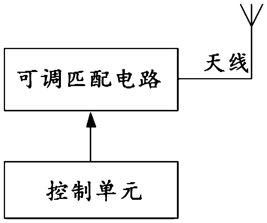
[0029] like figure 1 , figure 2 , Figure 5 An adjustable antenna matching circuit that varies with the load is shown, including: an adjustable matching circuit; and a control unit for acquiring the real-time load of the antenna and adjusting the capacitance value of the varactor diode in the matching circuit.

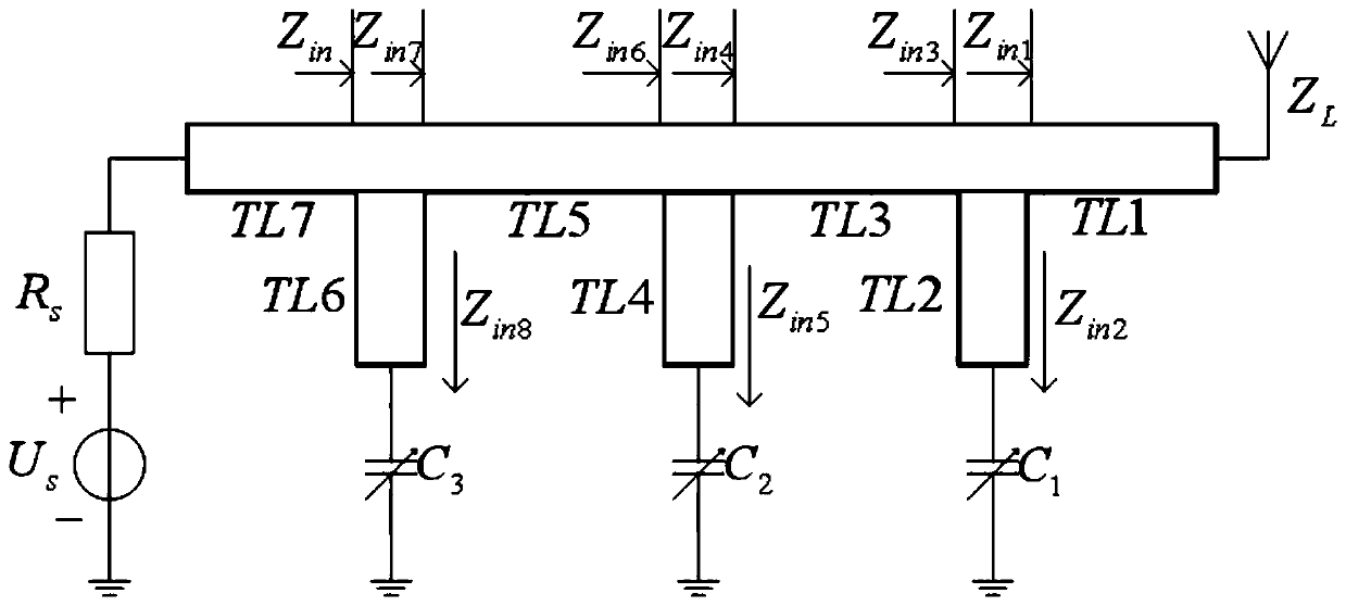
[0030] Figure 5It is a three-dimensional structural schematic diagram of a three-branch antenna matching circuit that changes with the load according to the present invention. The adjustable matching circuit includes a dielectric substrate 1, a 50Ω input microstrip connection line 2, a microstrip transmission line 3, a microstrip open-circuit branch 4, a varactor diode 5 and a capacitance bias circuit 6; wherein: the microstrip transmission line 3 includes a first ...


PUM


Abstract

The invention provides an antenna matching circuit. The circuit comprises an adjustable matching circuit connected with an antenna, and a control unit connected with the adjustable matching circuit; the adjustable matching circuit comprises a dielectric substrate, a 50-omega microstrip connecting line, a microstrip transmission line, a microstrip open-circuit branch, an adjustable varactor diode and a capacitor bias circuit; the control unit is used for obtaining the real-time load of the antenna and adjusting the capacitance value of the adjustable varactor diode; the 50-omega microstrip connecting line is an input microstrip connecting line; the microstrip transmission line comprises a first microstrip transmission line, a second microstrip transmission line and a third microstrip transmission line; and the microstrip open-circuit branch envelops the first microstrip open-circuit branch, the second microstrip open-circuit branch and the third microstrip open-circuit branch. Accordingto the invention, when the antenna load changes, the center frequency of the matching circuit can be adjusted, the real part change of the antenna load impedance is 50 omega, the imaginary part change is 50 omega, the output port can be matched in real time, and the antenna matching circuit has the advantages of being flexible in design and easy to tune.

Description

technical field [0001] The invention belongs to the field of microwave devices in electronic technology, in particular to an adjustable antenna matching circuit that changes with load, and a method for calculating variable capacitance by using an improved particle swarm algorithm. Background technique [0002] In wireless communication systems, the input impedance of an antenna is generally considered to be a constant value. However, in practical applications, the input impedance of the antenna varies due to different factors such as frequency, input power, and changes in the external environment. The mismatch between the antenna impedance and the front and back ends of the radio can greatly reduce the power and efficiency of the wireless link. A common solution is to implant a matching network between the antenna and the transmitter / receiver. The traditional matching is to insert a fixed matching network between the signal source and the antenna, which can only match the f...

Claims


Application Information

Patent Timeline
IPC IPC(8): H01Q5/10H01Q5/50H01Q23/00
CPCH01Q23/00H01Q5/10H01Q5/50
Inventor 宋智薛严冰李悦琳李熠娜
Owner DALIAN JIAOTONG UNIVERSITY
Why Eureka
Try Eureka