Atomizing rotary spray disc for fertilizer production and granulator

The technology of a granulator and spray disc is applied to the spray device with movable outlet, the spray device, the liquid is divided into bead droplets and other directions, which can solve the problems of easy nozzle blockage, nozzle blockage, inability to adapt to the high viscosity of the melt, etc. To achieve the effect of reducing the probability of solid impurity blockage and improving efficiency

Pending Publication Date: 2019-11-15
SHENZHEN BATIAN ECOTYPIC ENG
View PDF0 Cites 6 Cited by
  • Summary
  • Abstract
  • Description
  • Claims
  • Application Information

AI Technical Summary

Problems solved by technology

However, in the existing melt granulation process, the manufacturing process of spherical agricultural fertilizer particles cannot produce large-scale agricultural chemical fertilizers.
However, the coating and granulation process cannot adapt to the high viscosity and other characteristics of the melt due to the preparation of the existing mist-like molten slurry. The traditional pressure nozzle sprays the raw material melt from a nozzle hole. It is sprayed in a fan shape, and since the viscosity of the ternary compound fertilizer melt slurry is thousands or even tens of thousands of times that of the urea melt (the unit of viscosity is cps, the Chinese reads as centipoise, the melt viscosity of urea is only 2cps, The melt viscosity of the ternary balanced fertilizer can reach up to 500-800 million cps), and at the same time, because the phosphorus, potassium

Method used


Image

  • Atomizing rotary spray disc for fertilizer production and granulator
  • Atomizing rotary spray disc for fertilizer production and granulator
  • Atomizing rotary spray disc for fertilizer production and granulator

Examples


Embodiment 1

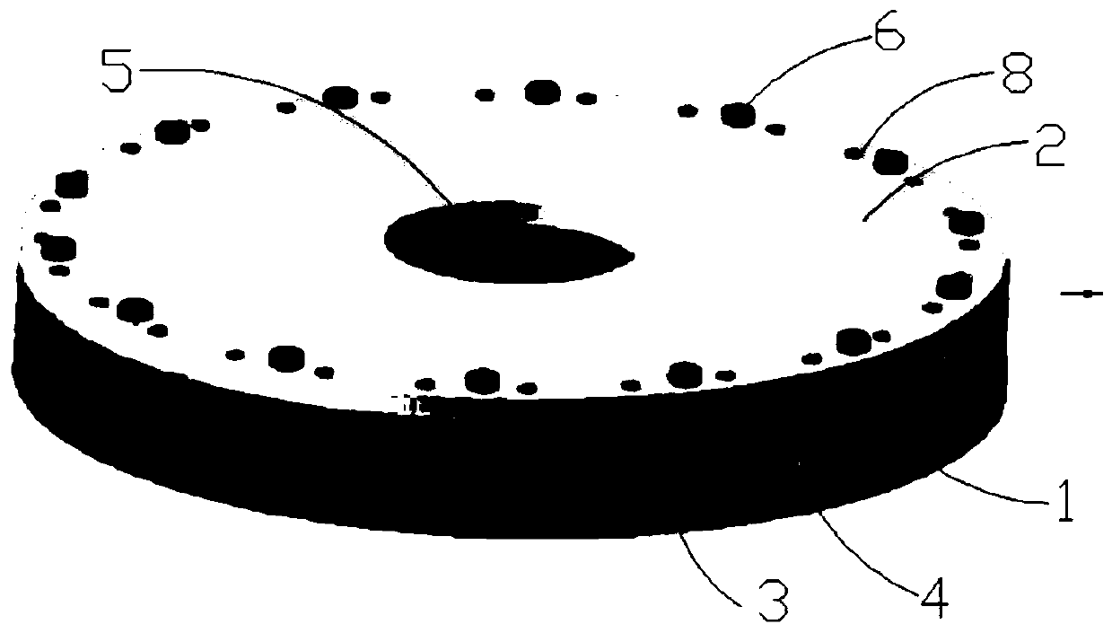
[0035] Such as Figure 1-5 As shown in and 7, an atomizing rotary spray pan 101 includes an upper end plate 2, a lower end plate 1 and a plurality of indexing blocks 3, and a plurality of indexing blocks 3 are evenly distributed at the peripheral edge positions of the lower end plate 1 , the upper end plate 2 is arranged on the indexing block 3 and fixedly connected with the indexing block 3 and the lower end plate 1, specifically, rivets are provided on the upper end plate 2, the lower end plate 1 and the indexing block 3 The hole 8, the upper end plate 2, the indexing block 3 and the lower end plate 1 are fixedly connected by rivets 6 to form a whole.

[0036] The side of the indexing block 3 facing the center of the lower end plate 1 is a protrusion 31, and the protrusion 31 gradually becomes wider from the center to both sides. In this embodiment, the protrusion 31 is a smooth arc protrusion Its cross-section is arc-shaped.

[0037] After the upper end plate 2, the lower...

Embodiment 2

[0044] The difference between this embodiment and Embodiment 1 is that the indexing block 3 is integrally formed with the lower end plate 1 , and then the indexing block 3 and the lower end plate 1 are fixed together with the upper end plate 2 by rivets 6 .

Embodiment 3

[0046] The difference between this embodiment and the above embodiment is that, if Figure 6 As shown, the protrusion 31 is a V-shaped protrusion with an isosceles triangle cross section, and the indexing block 3 and the lower end plate 1 are fixedly connected by rivets.


PUM

PropertyMeasurementUnit
Heightaaaaaaaaaa
Widthaaaaaaaaaa

Abstract

The invention discloses an atomizing rotary spray disc for fertilizer production. The atomizing rotary spray disc comprises a lower end plate, a plurality of indexing blocks and an upper end plate which are arranged from bottom to top; the plurality of indexing blocks are uniformly distributed at intervals at the peripheral edge positions of the lower end plate; the lower end plate, the pluralityof indexing blocks and the upper end plate define an inner cavity of the spray disc; the center of the upper end plate is provided with a molten liquid inlet; and the center of the lower end plate isconnected with an output shaft of a driving motor. Each indexing block of the atomizing rotary spray disc is convex and is widened from center to two sides in turn, and a backflow structure is formed,so that the molten liquid can be sprayed more smoothly. Rectangular nozzles have a certain width and height and rotate at a high speed to generate huge centrifugal force, so that the probability thatthe rectangular nozzles are blocked by solid impurities is greatly reduced.

Description

technical field [0001] The invention relates to the field of spray discs, in particular to an atomizing rotary spray disc in a spherical granulation production process. Background technique [0002] Agricultural chemical fertilizer is an essential nutrient element for plants. It can be used to improve soil properties and improve soil fertility. It is one of the material basis of agricultural production. [0003] The diameter of the spherical particles of the existing agricultural chemical fertilizer is about 2 mm, but in practical application, the fertilization effect of the agricultural chemical fertilizer particles between 2-10 mm is the best. But the manufacturing process of the spherical granules of agricultural chemical fertilizers in the existing melt granulation process can't make the agricultural chemical fertilizers of large particles. However, the coating and granulation process cannot adapt to the high viscosity and other characteristics of the melt due to the pr...

Claims


Application Information

Patent Timeline
IPC IPC(8): B01J2/04B05B3/10B05B13/02
CPCB01J2/04B05B3/10B05B13/0278
Inventor 孔亦周
Owner SHENZHEN BATIAN ECOTYPIC ENG
Why Eureka
Try Eureka