Upper limb uplifting assistance device

A power-assisted device and upper limb technology, applied in manipulators, program-controlled manipulators, manufacturing tools, etc., can solve the problems of users' shoulder discomfort, poor comfort, complex structure, etc., and achieve simple structure, light weight, and high wearing comfort Effect

Pending Publication Date: 2019-11-15
苏州瑞步康医疗科技有限公司
View PDF3 Cites 4 Cited by
  • Summary
  • Abstract
  • Description
  • Claims
  • Application Information

AI Technical Summary

Problems solved by technology

[0006] Therefore, the technical problem to be solved by the present invention is to overcome the disadvantages of the prior art, such as the complex structure, heavy weight, large volume and poor comfort of the user's shoulder discomfort caused by wearing the upper limb power assist device, so as to provide a simple structure , light weight, small size, fit the human body, high degree of freedom, flexible and reliable, comfortable to wear upper limb lifting assist device

Method used


Image

  • Upper limb uplifting assistance device
  • Upper limb uplifting assistance device
  • Upper limb uplifting assistance device

Examples


Embodiment 1

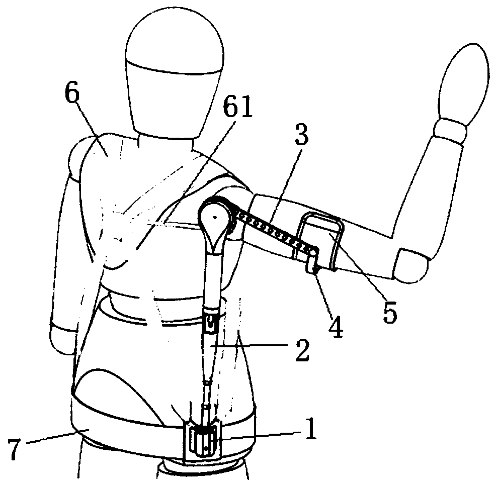
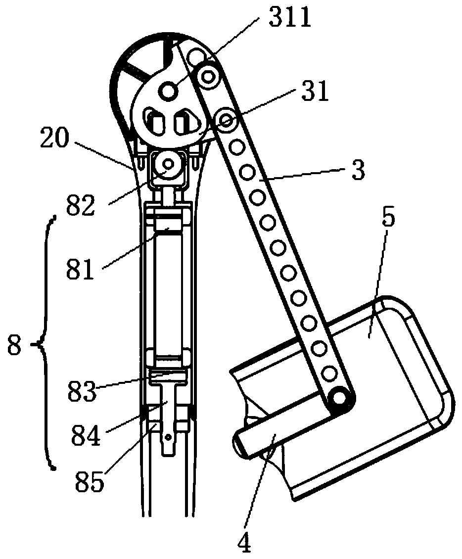
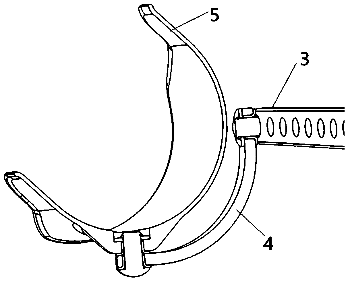
[0042] Such as figure 1 , figure 2A specific implementation of the upper limb lifting assisting device shown includes: a base joint 1, which is suitable for being fixed on a person's belt or torso; a rod one 2, whose first end is connected to the base joint 1, and is relatively The base joint 1 has degrees of freedom to rotate in three different directions in space, or in order to adapt to the free movement of the rod-2, on the basis that the rod-2 has three rotational degrees of freedom relative to the base joint 1, the rod-2 The base joint 1 as a whole can also have one or more translational degrees of freedom relative to the base joint 1; rod two 3, the first end of the rod two 3 is hinged to the second end of the rod one 2, There is at least one degree of freedom to rotate around the hinge axis of rod one 2 and rod two 3; the second end of the rod one 2 is provided with a transducer 81, and the top end of the transducer 81 has a bearing 82; The first end of bar two 3 is...

Embodiment 2

[0064] This embodiment provides an upper limb lifting assisting device, which is different from the upper limb lifting assisting device provided in Embodiment 1 in that a transducer is arranged inside the first end of the rod 2 3 , and the top end of the transducer There is a rolling bearing; the second end of the rod one 2 is fixed with a cam, and the axis of the cam is the hinge point between the rod two and the rod one, that is to say, the rod one 2 passes through the cam at its end Hinged with the rod two 3. It also realizes a 6-DOF mechanical arm connected to the upper limb of the human body through the mutual connection of the base joint, rod one, rod two, arm support rod, and arm support plate; When sagging naturally, the transducer of the booster energy storage device acts on the cam more than the axis of the cam, so no eccentric force will be generated, that is, in the non-working area below the chest, the transducer will not exert force on the arm, There is no impac...


PUM


Abstract

The invention relates to the technical field of human body assistance devices, in particular to an upper limb uplifting assistance device which comprises a base joint, a first rod, a second rod, an arm carrier rod and an arm carrier plate. The first rod is connected with the base joint. The second rod is hinged to the first rod. An energy converter is arranged in the first rod or the second rod. Abearing is arranged at the top end of the energy converter. A cam is fixedly arranged on the second rod or the first rod. The axis of the cam coincides with the hinge point of the second rod and thefirst rod. The rolling bearing is connected with the curve surface of the cam in an abutting-against manner. By the adoption of the cam structure, when the arm droops, acting force of the energy converter to the cam passes through the axis of the cam, accordingly, torque is not generated to the cam, and thus obstruction to natural drooping of the arm is avoided. When the arm is lifted up gradually, the acting force of the energy converter to the cam deviates from the axis of the cam gradually, torque is generated to the cam, the torque pushes the second rod to be lifted upwards, and upliftingassistance to the arm is achieved. Stress supporting points of the base joint are distributed on the waist, and thus the situation that due to long-time use, the shoulders of a user are uncomfortableis avoided.

Description

technical field [0001] The invention relates to the technical field of human body assisting devices, in particular to an upper limb lifting assisting device. Background technique [0002] In factories, warehouses, construction sites and other working scenarios, workers need to lift heavy objects for a long time or more frequently. Long-term, repetitive, and high-intensity labor operations can cause musculoskeletal disorders of the upper limbs. [0003] In order to reduce the damage caused by long-term, repeated, and high-intensity operations to the human body, the existing technical solution is to provide an upper limb power-assist device, which provides power through the power-assisted support structure tied to the upper limb of the human body, so as to reduce the force on the bones of the upper limb , to avoid upper extremity musculoskeletal disorders. For example, the numbers are CN109571435A, CN 208914104U, CN107835675A and other patents. [0004] In the patent docume...

Claims


Application Information

Patent Timeline
Patent Type & Authority Applications(China)
IPC IPC(8): B25J9/00
CPCB25J9/0006
Inventor 王世乾
Owner 苏州瑞步康医疗科技有限公司
Why Eureka
Try Eureka