
PLC-based swimming pool circulating water treatment system

A technology of treatment system and circulating water, applied in multi-stage water treatment, water/sewage treatment, water treatment parameter control, etc. It can solve the problems of wasting water resources, producing algae, and general treatment effect, and achieving good purification effect. Effect

Inactive Publication Date: 2019-11-15
程思铭
View PDF7 Cites 2 Cited by
  • Summary
  • Abstract
  • Description
  • Claims
  • Application Information

AI Technical Summary

Problems solved by technology

[0002] With the continuous development of economy and society and the continuous improvement of people's living standards, swimming pools for leisure and fitness are becoming more and more popular. Urine and pollutants on the surface of the human body, etc. These substances will make the swimming pool turbid, and algae will be produced after a long time. If it is not purified and disinfected in time, it may cause harm to the human body. Therefore, the swimming pool needs to be treated regularly. Make the swimming pool sustainable
[0003] Some swimming pools use the method of draining all dirty water and replacing it with new water. This method wastes water resources and does not meet the requirements of sustainable development.
In addition, some swimming pools use sand filter + chlorine disinfection. When the water quality cannot meet the requirements, all you can do is to add a large amount of chlorine. As a result, the swimming pool water contains relatively high chlorine. Swimming will irritate people's skin and eyes. In addition, although the above methods can play a certain role in purification, there will still be urea, oil and other substances in the treated water, and the treatment effect is average.

Method used


Image

  • PLC-based swimming pool circulating water treatment system
  • PLC-based swimming pool circulating water treatment system
  • PLC-based swimming pool circulating water treatment system

Examples


Embodiment 1

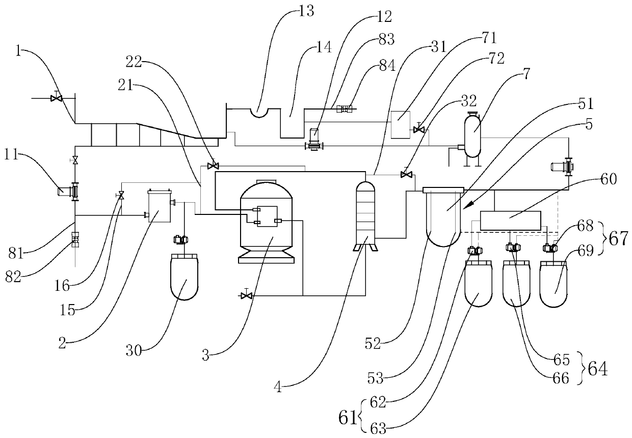
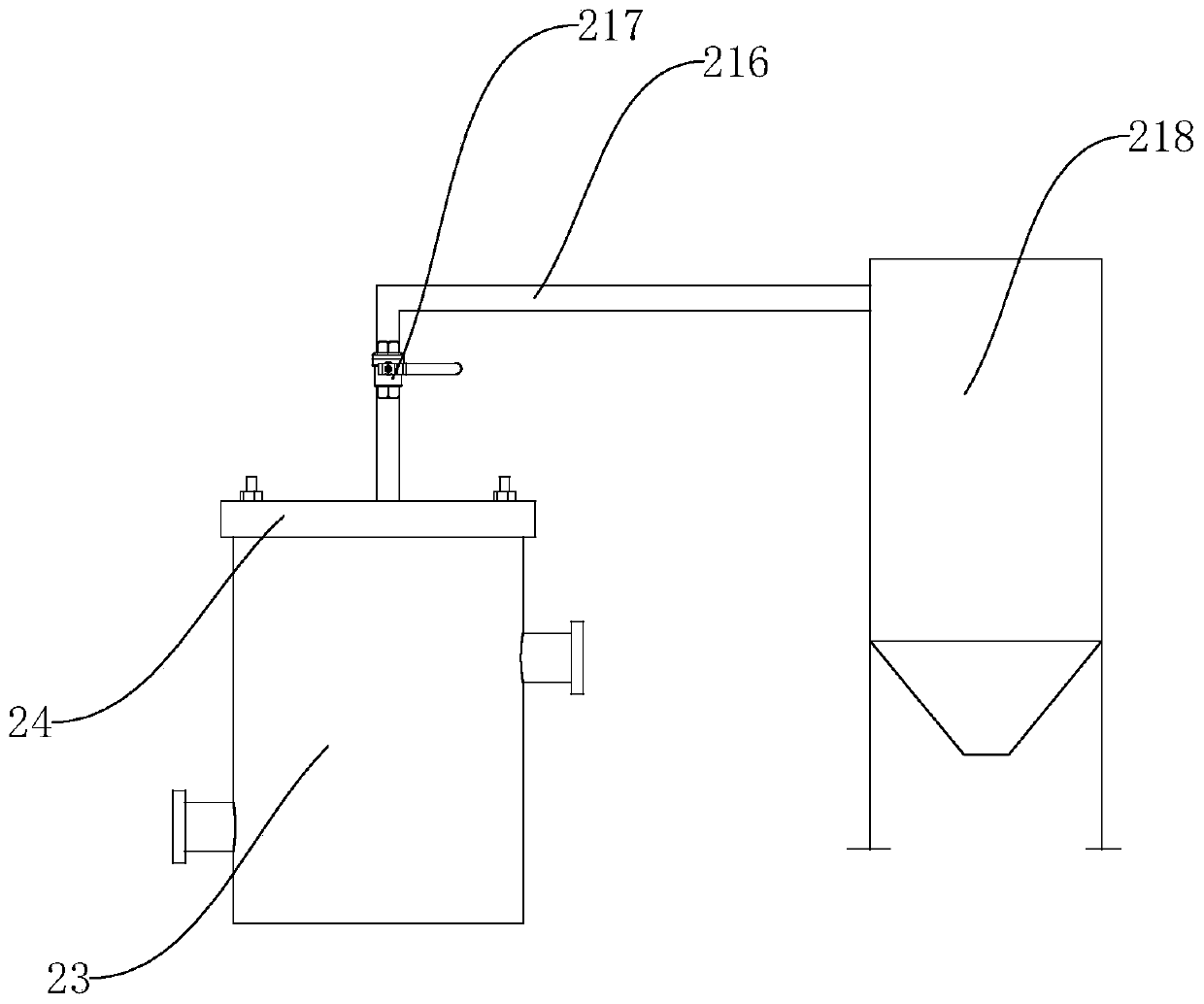
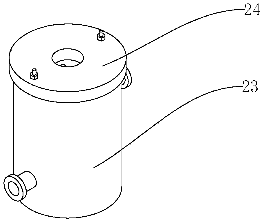
[0030] Embodiment 1: As shown in the figure, a PLC-based swimming pool 1 circulating water treatment system includes a swimming pool 1, and also includes a first circulating pump 11, a hair collector 2, a filter sand tank 3, a multimedia filter device 4, and urea Treatment device 5, water quality monitor 60, disinfectant injection device 61, first PH adjustment device 64, second PH adjustment device 67, heat exchanger 7, second circulation pump 12, overflow tank 13 and balance pool 14, swimming pool The bottom of 1 is provided with a plurality of drainage outlets, and the anti-vortex embedded parts 9 are installed at the plurality of drainage outlets, and the plurality of drainage outlets are respectively connected with the inlet of the first circulation pump 11, and the outlet of the first circulation pump 11 is connected with the hair collection The inlet of the device 2 is connected, the outlet of the hair collector 2 is connected with the inlet of the filter sand tank 3, an...

Embodiment 2

[0032] Embodiment 2: As shown in the figure, other structures are the same as Embodiment 1, and the difference is that the outlet of the first circulation pump 11 is also connected with a first overflow pipe 81, and the first overflow pipe 81 is equipped with a second A solenoid valve 82, the outlet of the balance pool 14 is provided with a second overflow pipe 83, a second solenoid valve 84 is installed on the second overflow pipe 83, a liquid level sensor 85 is fixed on the side wall of the swimming pool 1, and the liquid level sensor 85 is electrically connected to the PLC controller 86, and the first electromagnetic valve 82 and the second electromagnetic valve 84 are electrically connected to the PLC controller 86 respectively. In this structure, the swimming pool 1 is connected with the external water supply system, and the liquid level sensor 85 is fixed on the upper part of the side wall of the swimming pool 1. When it detects that the water in the swimming pool 1 excee...

Embodiment 3

[0034]Embodiment 3: As shown in the figure, other structures are the same as Embodiment 2, and the difference is that the multimedia filter device 4 includes a filter tower 41 and a first filter layer 42 filled in the filter tower 41 from top to bottom, The second filter layer 43, the third filter layer 44 and the fourth filter layer 45, the inlet of the multimedia filter device 4 is arranged on the top of the filter tower 41, and the outlet of the multimedia filter device 4 is arranged at the bottom of the filter tower 41, the first The filter layer 42 is formed by mixing anthracite particles and magnetic filter particles, the mass ratio of anthracite particles to magnetic filter particles is 100: (15-30), the second filter layer 43 is composed of quartz sand, and the third filter layer 44 is made of modified Composed of activated carbon particles and sepiolite, the mass ratio of modified activated carbon particles to sepiolite is 100: (25-40), and the fourth filter layer 45 i...


PUM

PropertyMeasurementUnit
porosityaaaaaaaaaa

Abstract

The invention discloses a PLC-based swimming pool circulating water treatment system. The system comprises a swimming pool, and further comprises a first circulating pump, a hair collector, a filter sand cylinder, a multi-medium filtering device, a urea treatment device, a water quality monitor, a disinfectant feeding device, a first PH adjusting device, a second PH adjusting device, a heat exchanger, a second circulating pump, an overflow tank and a balance tank. A plurality of drainage ports are formed in the bottom of the swimming pool, anti-vortex embedded parts are installed at the drainage ports, the drainage ports are communicated with an inlet of the first circulating pump, an outlet of the first circulating pump is communicated with an inlet of the hair collector, an outlet of thehair collector is communicated with an inlet of the filter sand cylinder, a flocculating agent feeding device is further arranged between the hair collector and the filter sand cylinder, and an outlet of the filter sand cylinder is communicated with an inlet of the multi-medium filtering device. The system has the advantages that water in the swimming pool can be circularly purified, water resources are saved, and the purification effect is good.

Description

technical field [0001] The invention relates to a water treatment system, in particular to a PLC-based swimming pool circulating water treatment system. Background technique [0002] With the continuous development of economy and society and the continuous improvement of people's living standards, swimming pools for leisure and fitness are becoming more and more popular. Urine and pollutants on the surface of the human body, etc. These substances will make the swimming pool turbid, and algae will be produced after a long time. If it is not purified and disinfected in time, it may cause harm to the human body. Therefore, the swimming pool needs to be treated regularly. Make the swimming pool can continue to use. [0003] Some swimming pools use the method of draining all the dirty water and replacing it with new water. This method wastes water resources and does not meet the requirements of sustainable development. In addition, some swimming pools use sand filter + chlorine...

Claims


Application Information

Patent Timeline
Patent Type & Authority Applications(China)
IPC IPC(8): C02F9/10C02F103/42
CPCC02F1/001C02F1/02C02F1/281C02F1/283C02F1/46104C02F1/50C02F1/5281C02F1/66C02F9/00C02F2103/42C02F2201/002C02F2201/005C02F2201/4614C02F2209/005C02F2209/02C02F2209/11C02F2209/14C02F2209/42C02F2301/046C02F2301/08
Inventor 程思铭
Owner 程思铭
Learn More