Intelligent pipeline for fluid monitoring

A technology of intelligent pipelines and pipelines, applied in fluid velocity measurement, pipeline systems, fluid dynamics tests, etc., can solve problems such as environmental pollution, economic losses, and small monitoring range, so as to avoid mutual interference, increase sensitivity, and ensure accuracy sexual effect

Pending Publication Date: 2019-11-15
ZHEJIANG UNIV OF TECH
View PDF0 Cites 1 Cited by
  • Summary
  • Abstract
  • Description
  • Claims
  • Application Information

AI Technical Summary

Problems solved by technology

It can be said that the pipeline is the lifeline of these industries. However, due to the huge characteristics and complexity of the pipeline system, the state monitoring of the fluid or gas in the pipeline has become a difficult problem. Every year, some large and small accidents are caused by the lack of relevant monitoring. Countless, such as in the field of oil and gas, the consequences are not only economic losses, but also bring huge pollution to the environment
[0003] Traditional pipeline monitoring mainly judges the state of the fluid through manual inspection and periodic inspection of the material state in the pipe. These methods are not only time-consuming and labor-intensive but also lack timeliness. It is difficult to quickly and quickly find relevant problems and monitor them in real time.
With the development of technology, some new technologies have emerged, such as through the analysis of fluid mass and volume in the pipeline, electromagnetic analysis, pipeline pressure analysis, etc., among which methods similar to mass and volume analysis are often equal to the state of the fluid in the pipeline. It can only be monitored after changes have occurred or some faults have occurred. The main problem of the latter two methods is that they lack certain advantages in real-time monitoring. At the same time, the monitoring range is small, and the equipment requires regular maintenance. Some disadvantages of these technologies

Method used


Image

  • Intelligent pipeline for fluid monitoring
  • Intelligent pipeline for fluid monitoring
  • Intelligent pipeline for fluid monitoring

Examples


Embodiment

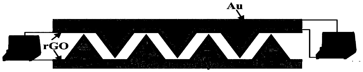
[0074] The data acquisition module of this embodiment is a piezoelectric / piezoresistive dual-mode flexible sensor, and its microarray structure adopts a pyramid-shaped microarray with a base length of 60 μm and a height of 40 μm. Such as figure 2 The shown piezoelectric / piezoresistive dual-mode pressure sensor includes a piezoelectric layer and a piezoresistive layer. Gold electrodes are prepared on the upper and lower sides of the piezoelectric layer, and the piezoelectric signal output by the piezoelectric layer is connected to a voltmeter through the gold electrodes. The surface of the microstructure of the piezoelectric layer and the piezoresistive layer is covered with a layer of rGO. The piezoresistive signal is input to the ammeter through two layers of rGO. The sensing signals of the piezoelectric layer and the piezoresistive layer are output through different electrodes, which avoids the mutual interference of the two sets of signals and ensures the accuracy of the...


PUM


Abstract

The invention provides an intelligent pipeline for fluid monitoring. The intelligent pipeline comprises a pipeline, a data acquisition module, a data processing module, a wireless transmitting module,a wireless receiving module, a display screen and a power supply module. The power supply module, the data acquisition module and the wireless transmission module are connected in sequence; the dataacquisition module is vertically fixed on the inner wall of the pipeline; the power supply module and the wireless transmitting module are hermetically fixed on the upper wall of the inner side of thepipeline; and the wireless receiving module, the data processing module and the display screen are sequentially connected and fixed on the outer side of the pipeline. The data acquisition module is bent and deformed along with the movement of the fluid, and then an electric signal related thereto is generated, so that the state of the fluid in the pipeline is monitored. Fluid state signals whichare difficult to collect by the conventional pipeline system can be effectively detected and monitored, and the intelligent pipeline is suitable for pipeline system requirements in many complex states.

Description

technical field [0001] The invention belongs to the field of intelligent pipelines, in particular to an intelligent pipeline for fluid monitoring. Background technique [0002] In industrial production and life, the pipeline system is widely used in various industries and fields due to its own characteristics, such as the transportation of solid particles, powder, slurry, fluid, gas, etc. In actual industrial production, pipeline systems play an extremely important role in important specific scenarios such as petrochemical transportation, sewage treatment, and natural gas transportation. It can be said that the pipeline is the lifeline of these industries. However, due to the huge characteristics and complexity of the pipeline system, the state monitoring of the fluid or gas in the pipeline has become a difficult problem. Every year, some large and small accidents are caused by the lack of relevant monitoring. Countless, such as in the field of oil and gas, the consequences...

Claims


Application Information

Patent Timeline
Patent Type & Authority Applications(China)
IPC IPC(8): G01P5/08G01P13/02G01P13/00G01M10/00F17D5/00G08C17/02
CPCF17D5/00G01M10/00G01P5/08G01P13/0053G01P13/02G08C17/02
Inventor 吴化平孔琨裘烨王有岩蒋正扬王怡超
Owner ZHEJIANG UNIV OF TECH
Why Eureka
Try Eureka