
Radar antenna for ship traffic management system

A technology of ship traffic management and radar antenna, which is applied in the field of radar electronic equipment, can solve the problems that it is difficult to meet the application requirements of modern water area scene monitoring, increase the work of antenna maintenance and upgrading, energy consumption and high manufacturing cost, and achieve light weight and security The effect of scanning speed and low manufacturing cost

Pending Publication Date: 2019-11-15
ANHUI SUN CREATE ELECTRONICS
View PDF0 Cites 1 Cited by
  • Summary
  • Abstract
  • Description
  • Claims
  • Application Information

AI Technical Summary

Problems solved by technology

The current radar antenna box adopts a ribbed frame structure, which has a complex structure, a large number of parts, heavy weight and large size, which often affects the high-speed rotation of the radar antenna, which in turn makes the radar antenna more difficult to observe. The scanning speed of the area becomes slower, and it also leads to higher energy consumption and manufacturing costs, which increases the difficulty of antenna maintenance and upgrading
With the continuous increase of water flow, the requirements for the effective management of various ships in the water area have become increasingly prominent, and the requirements for various performance indicators of radar antennas, especially the technical indicators such as the external dimensions, weight, and wind load area of ​​the box, have been increasing. Traditional radar antennas The structure has been difficult to meet the application requirements of modern water surface monitoring

Method used


Image

  • Radar antenna for ship traffic management system
  • Radar antenna for ship traffic management system
  • Radar antenna for ship traffic management system

Examples

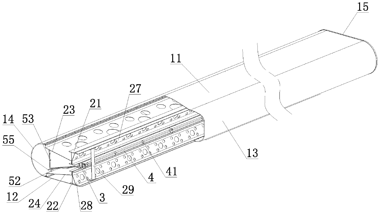
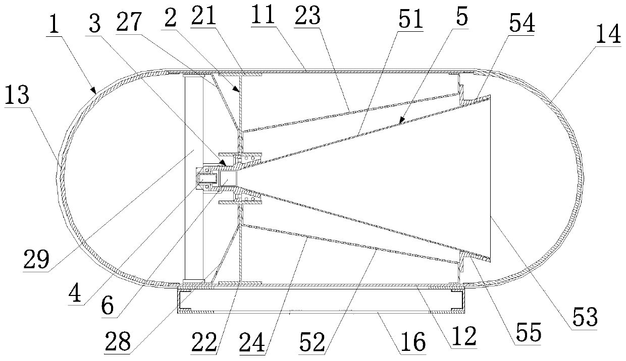
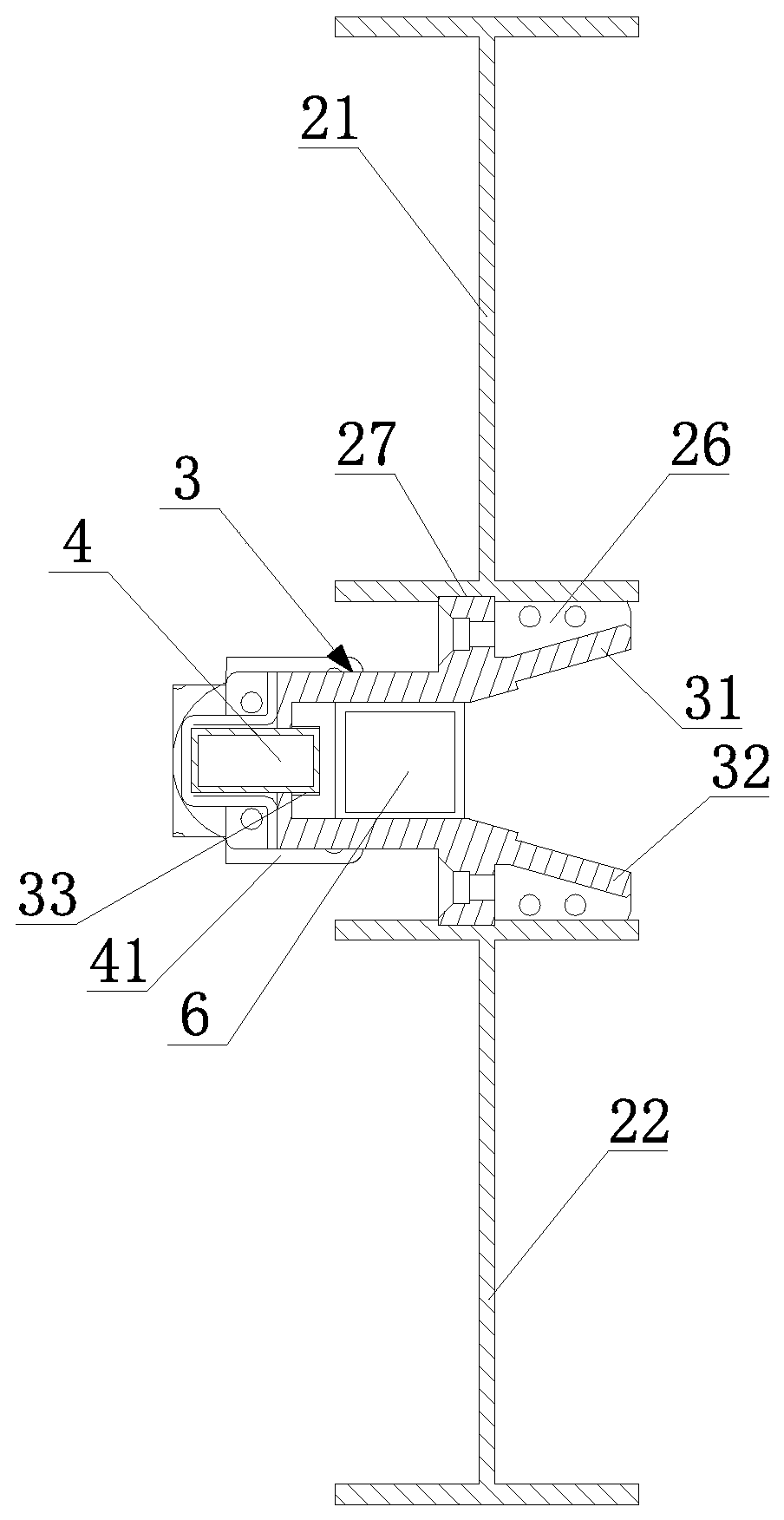

Embodiment Construction

[0025] The following will clearly and completely describe the technical solutions in the embodiments of the present invention with reference to the accompanying drawings in the embodiments of the present invention. Obviously, the described embodiments are only some, not all, embodiments of the present invention. Based on the embodiments of the present invention, all other embodiments obtained by persons of ordinary skill in the art without making creative efforts belong to the protection scope of the present invention.

[0026] Such as figure 1 , figure 2 , image 3 As shown, a radar antenna for a ship traffic management system includes a box body 1 and a skeleton assembly 2 arranged in the box body 1, a polarization grid 3, a waveguide 4 and a wing plate assembly 5; the polarization grid Both the grid 3 and the wing assembly 5 are fixed on the box body 1 through the skeleton assembly 2, and the waveguide 4, the wing assembly 5 and the feed network 6 are all arranged on the...


PUM


Abstract

The invention relates to a radar antenna for a ship traffic management system. The radar antenna comprises a box body, a skeleton component, a polarization grid, a waveguide and a wing plate component, wherein the skeleton component, the polarization grid, the waveguide and the wing plate component are arranged in the box body. The polarization grid and the wing plate component are fixed on the box body through the skeleton component. The waveguide, the wing plate component and a feeding network are all arranged on a polarization grid. The waveguide is connected with the feeding network. The box body comprises a top plate and a bottom plate. A windshield and a radome are arranged on both ends in the width direction of the top plate and the bottom plate respectively. Side plates are arranged on both ends in the length direction of the top plate and the bottom plate. The skeleton component is fixedly connected with the top plate and the bottom plate. The polarization grid and the waveguide are arranged near the windshield. The wing plate component is arranged near the radome. The radar antenna provided by the invention has the advantages of light weight and simple structure, which ensures the scanning speed of the radar antenna to an observation area, and improves the working performance of the radar antenna.

Description

technical field [0001] The invention belongs to the field of radar electronic equipment, and in particular relates to a radar antenna used in a ship traffic management system. Background technique [0002] With the development of my country's shipping industry, traditional vessel traffic management methods have been difficult to meet the increasing traffic volume. Therefore, the maritime departments of domestic large and medium-sized ports have introduced Vessel Traffic Management System (VTS, VesselTraffic Services). The Vessel Traffic Management System (VTS) is a comprehensive maritime management and service platform, which undertakes multiple functions such as information service, navigation aid service, and traffic organization. It has played an important role in maintaining safety, maintaining good water traffic order, protecting the marine environment, preventing environmental pollution in water areas, and coordinating emergency search and rescue operations. As an imp...

Claims


Application Information

Patent Timeline
IPC IPC(8): H01Q1/22H01Q1/42
CPCH01Q1/42H01Q1/22
Inventor 李成丁飞高志辉董青
Owner ANHUI SUN CREATE ELECTRONICS
Learn More