Array antenna subarray, array antenna module and array antenna

An array antenna and antenna sub-array technology, applied in the field of array antenna sub-array, array antenna module and array antenna, can solve the problems affecting the overall electrical performance of the phased array antenna, low isolation of the phased array transceiver antenna, etc., to achieve compact Spatial layout, optimal circular polarization function, and the effect of improving isolation

Pending Publication Date: 2019-11-15
CHENGDU T-RAY TECH CO LTD
View PDF0 Cites 10 Cited by
  • Summary
  • Abstract
  • Description
  • Claims
  • Application Information

AI Technical Summary

Problems solved by technology

[0004] This application provides an array antenna sub-array, an array antenna module, and an array antenna, which are used to solve the problem of low isolation between phased array transceiver antennas caused by unreasonable spatial layout of phased array antennas in the prior art. Technical Issues Affecting the Overall Electrical Performance of Phased Array Antennas

Method used


Image

  • Array antenna subarray, array antenna module and array antenna
  • Array antenna subarray, array antenna module and array antenna
  • Array antenna subarray, array antenna module and array antenna

Examples


Embodiment 1

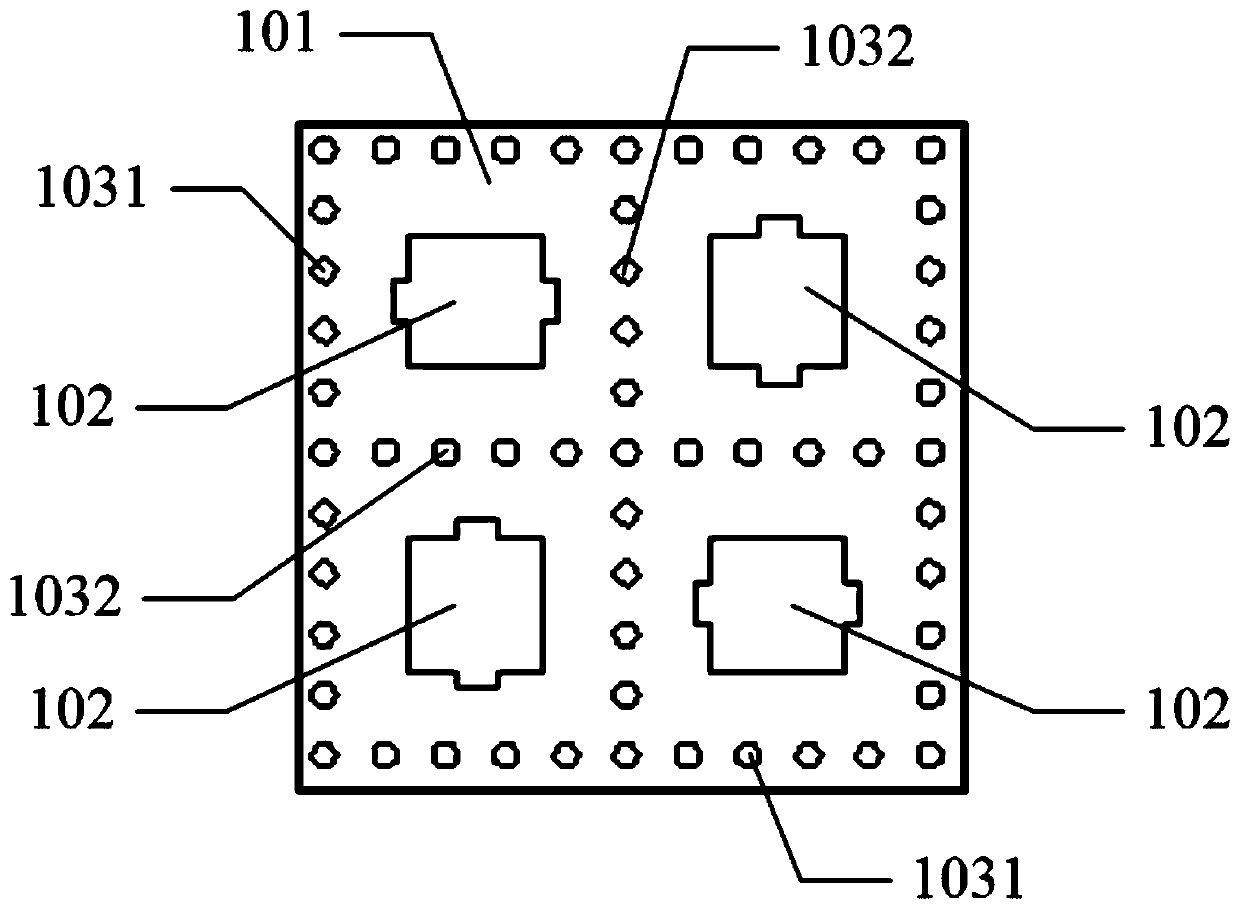
[0039] Please refer to figure 1 , Embodiment 1 of the present application provides an array antenna sub-array, including:

[0040] The first dielectric substrate 101;

[0041] At least two element antennas 102 are arranged on the surface of the first dielectric substrate 101, wherein the at least two element antennas 102 surround the first center of the surface of the first dielectric substrate 101, and adjacent elements The rotation angle difference between the antennas 102 is 360° / N, wherein each unit antenna 102 is the same, and the distance between each antenna unit 102 and the first center is the same, and N is an integer greater than or equal to 1.

[0042] In the embodiment of this application, the unit antenna can be as figure 1 In the shown pattern, the number N of unit antennas is 4, then the rotation angle difference between adjacent unit antennas is 360° / 4=90°, and the four unit antennas can be arranged in four corners of the central point in a matrix distributio...

Embodiment 2

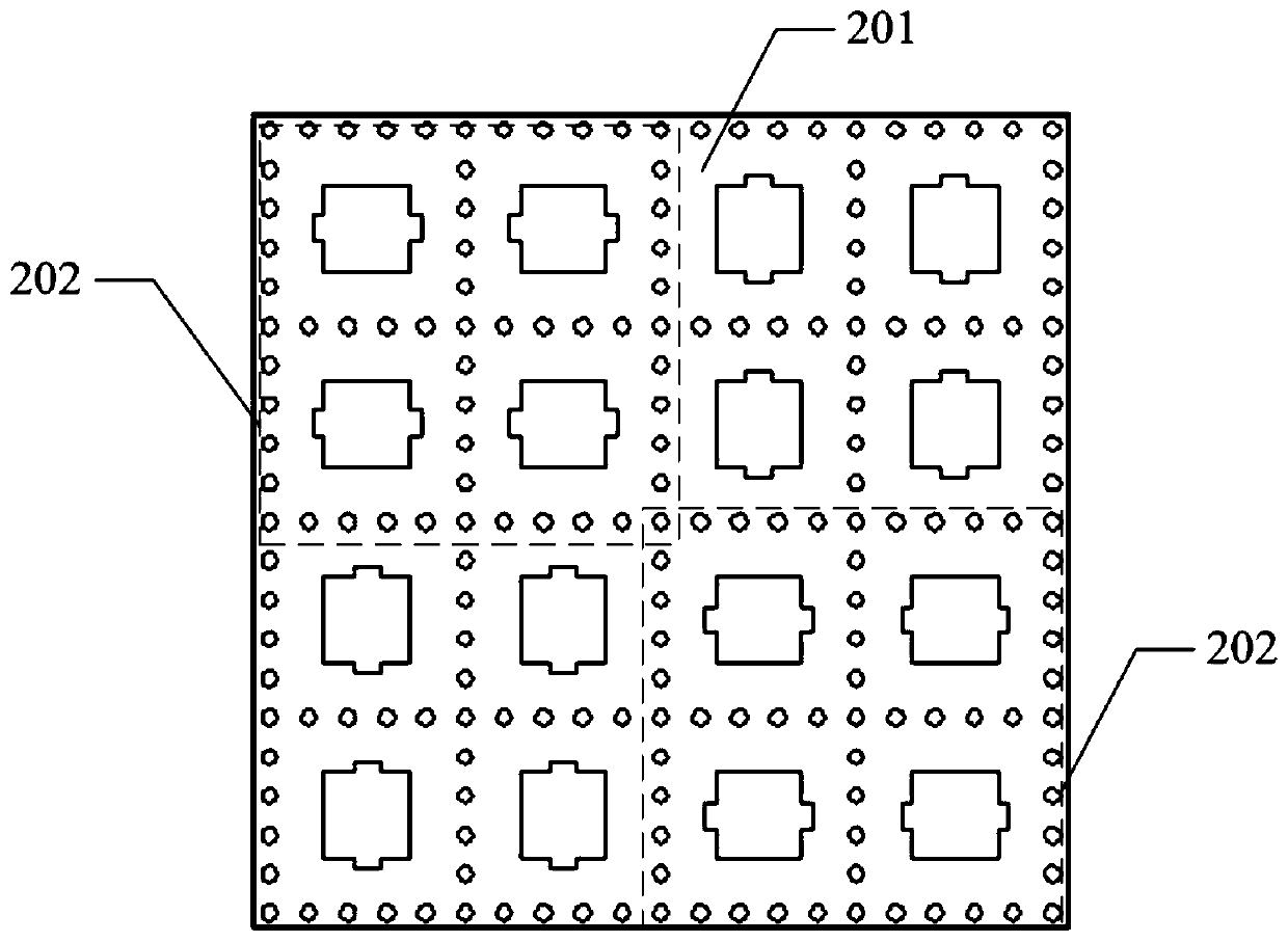
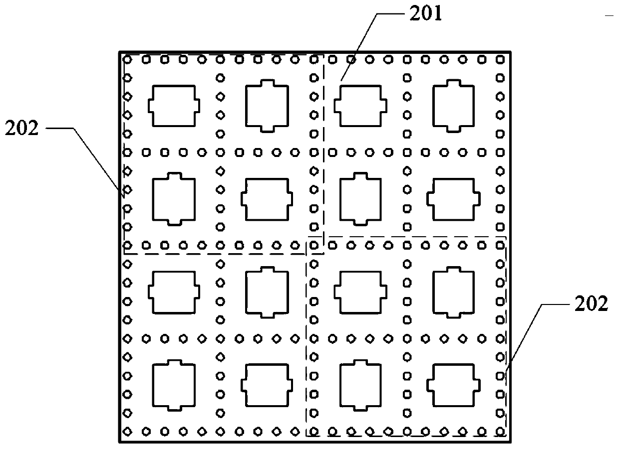
[0053] Please refer to FIG. 2(a) and FIG. 2(b). Embodiment 2 of the present application provides an array antenna module, including:

[0054] The second dielectric substrate 201;

[0055] At least two sub-array units 202 are arranged on the surface of the second dielectric substrate 201, the at least two sub-array units 202 surround the second center of the surface of the second dielectric substrate 201, adjacent sub-array units 202 The rotation angle difference between them is 360° / Q, each sub-array unit 202 is the same, and the distance between each sub-array unit 202 and the second center is the same, and Q is an integer greater than or equal to 1;

[0056] Wherein, the sub-array unit 202 is an antenna sub-array in which the antenna units are evenly distributed in the same direction (as shown in FIG. array (as shown in Figure 2(b)).

[0057] aforementioned figure 1 The various changes and specific examples of the array antenna sub-array in the embodiment are also applica...

Embodiment 3

[0059] Please refer to image 3 , Embodiment 3 of the present application provides an array antenna, including:

[0060] The first array antenna module 301 as described in Embodiment 2; and / or,

[0061] The second array antenna module 302 according to the second embodiment, wherein, the first array antenna module 301 and the second array antenna module 302 are on the same side surface of the same substrate, and the first array antenna module The first sub-array unit in 301 is an antenna sub-array in which the antenna units are evenly distributed in the same direction, and the second sub-array unit in the second array antenna module 302 is an antenna unit whose direction is different from that of the first sub-array unit. An antenna sub-array: at least two metal baffles 303 are arranged between the first array antenna module 301 and the second array antenna module 302 .

[0062] In an actual working process, the first array antenna module 301 can be used for wireless signal r...


PUM


Abstract

The invention discloses an array antenna subarray, an array antenna module and an array antenna. At least two unit antennas are arranged on the surface of a dielectric substrate, the at least two unitantennas surround a first center of the surface of the dielectric substrate, and the rotation angle difference between adjacent unit antennas is 360 degrees/N. Meanwhile, each unit antenna is the same, and the distance between each antenna unit and the first center is the same. The antenna subarray arranged by adopting the above mode has very compact spatial arrangement after being assembled intoa phased array antenna, and a better circular polarization function can be achieved. In addition, metal vias can also be arranged around each unit antenna and between two adjacent unit antennas, so that the isolation of the whole phased array antenna is improved on the basis of improving the isolation between the unit antennas, thereby having the technical effects of improving the overall electrical performance of the phased array antenna and improving the wide-angle scanning ability of the phased array antenna.

Description

technical field [0001] The invention relates to the field of microwave and millimeter wave array antennas, in particular to an array antenna sub-array, an array antenna module and an array antenna. Background technique [0002] Microstrip patch antennas are increasingly being widely used in the field of communication because of their advantages of small size, light weight, low profile, and easy conformality with various carriers. Splicing microstrip patch antennas according to a specific layout can become a phase-controlled Array array antenna, phased array antenna using electronic scanning technology has the characteristics of fast scanning speed and high beam pointing accuracy. However, the antenna performance obtained by the current phased array layout is often not optimal. When the phased array antenna is used in an environment with limited space or conditions, it is often due to the difference between the antenna array used to receive signals and the antenna array used ...

Claims


Application Information

Patent Timeline
Patent Type & Authority Applications(China)
IPC IPC(8): H01Q1/38H01Q1/52H01Q15/24H01Q17/00H01Q21/06H01Q21/20
CPCH01Q1/38H01Q1/521H01Q1/523H01Q15/24H01Q17/00H01Q21/065H01Q21/20
Inventor 吴祖兵郭凡玉颜微张琳王建伟赵国华
Owner CHENGDU T-RAY TECH CO LTD
Why Eureka
Try Eureka