A Method for Improving the Uniformity of Stator Axial Temperature Distribution

A technology of temperature distribution and uniformity, applied in the direction of magnetic circuit shape/style/structure, electromechanical devices, electrical components, etc., can solve the problem that the axial temperature difference between the stator coil and the iron core cannot be effectively reduced, and the axial wind speed of the stator air ditch is uneven. and other problems, to ensure the reliability and stability of use, easy adjustment, and simple operation.

Active Publication Date: 2020-11-03
DONGFANG ELECTRIC MACHINERY
View PDF9 Cites 0 Cited by
  • Summary
  • Abstract
  • Description
  • Claims
  • Application Information

AI Technical Summary

Problems solved by technology

[0006] The motor with ventilation slots in the stator disclosed in this patent document can increase the axial ventilation volume inside the motor, but the axial wind speed in the stator air groove is not uniform, and thus cannot effectively reduce the axial temperature difference between the stator coil and the iron core

Method used


Image

  • A Method for Improving the Uniformity of Stator Axial Temperature Distribution
  • A Method for Improving the Uniformity of Stator Axial Temperature Distribution

Examples


Embodiment 1

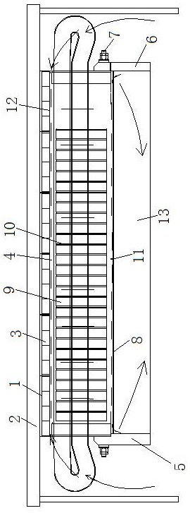
[0035] see figure 1 and figure 2 , a method for improving the uniformity of stator axial temperature distribution, comprising the following steps:

[0036] a. Install the stator axial temperature distribution uniformity device on the wind turbine;

[0037] b. Install stator pressure plate one 5, stator pressure plate two 6, axial ring plate 8, circumferential ring plate 11 and stator core 4 of the stator axial temperature distribution uniformity device, and place the circumferential ring plate 11 and axial ring plate 8 between The included angle is set at 85°, forming a space 13 at the back of the stator core;

[0038] c. The airflow flowing through the back space 13 of the stator core is set so that the airflow flowing through the stator-rotor gap 12 has the same flow rate and the opposite flow direction at the same axial position.

Embodiment 2

[0040] see figure 1and figure 2 , a method for improving the uniformity of stator axial temperature distribution, comprising the following steps:

[0041] a. Install the stator axial temperature distribution uniformity device on the wind turbine;

[0042] b. Install stator pressure plate one 5, stator pressure plate two 6, axial ring plate 8, circumferential ring plate 11 and stator core 4 of the stator axial temperature distribution uniformity device, and place the circumferential ring plate 11 and axial ring plate 8 between The included angle is set at 90° to form a back space 13 of the stator core;

[0043] c. The airflow flowing through the back space 13 of the stator core is set so that the airflow flowing through the stator-rotor gap 12 has the same flow rate and the opposite flow direction at the same axial position.

Embodiment 3

[0045] see figure 1 and figure 2 , a method for improving the uniformity of stator axial temperature distribution, comprising the following steps:

[0046] a. Install the stator axial temperature distribution uniformity device on the wind turbine;

[0047] b. Install stator pressure plate one 5, stator pressure plate two 6, axial ring plate 8, circumferential ring plate 11 and stator core 4 of the stator axial temperature distribution uniformity device, and place the circumferential ring plate 11 and axial ring plate 8 between The included angle is set at 95°, forming a space 13 at the back of the stator core;

[0048] c. The airflow flowing through the back space 13 of the stator core is set so that the airflow flowing through the stator-rotor gap 12 has the same flow rate and the opposite flow direction at the same axial position.


PUM


Abstract

The invention discloses a method for improving the axial temperature distribution uniformity of a stator, and belongs to the technical field of generators. The method is characterized by comprising the steps of a, installing a stator axial temperature distribution uniformity device on a wind driven generator; b, installing and arranging a stator pressing plate I, a stator pressing plate II, an axial annular plate, a circumferential annular plate and a stator core of the stator axial temperature distribution uniformity device, setting an included angle between the circumferential annular plateand the axial annular plate to be 85-95 degrees, and forming a back space of the stator core; and c, setting an air flow circulating in the back space of the stator core to be the same in flow rate and opposite in flow direction with an air flow circuiting in the clearance between the stator and the rotor at the same axial position. According to the invention, the static pressure difference can bemaintained at a fixed value, the axial wind speed of a stator wind channel is relatively uniform, the operation is simple, the adjustment is easy, the axial temperature difference between the statorcoil and the iron core can be effectively reduced, and the reliability and the stability of the generator are guaranteed.

Description

technical field [0001] The invention relates to the technical field of generators, in particular to a method for improving the uniformity of axial temperature distribution of a stator. Background technique [0002] For large rotating electrical machines, it is a very common cooling method to arrange a certain number of ventilation grooves on the stator to cool the stator coil and iron core. Cooperate with other structures to form different flow patterns. Among them, the air flow diverges from the air gap to the stator air groove, which is the same as the flow in most cases in the motor, which is called positive flow; the air flow converges from the stator air groove to the air gap, which is opposite to the flow in most cases in the motor, which is called reverse flow . [0003] For the actual structure of the motor, the space at the back of the air duct is generally large, and it can be considered that the pressure remains unchanged. As for the air gap, the flow space is u...

Claims


Application Information

Patent Timeline
Patent Type & Authority Patents(China)
IPC IPC(8): H02K1/20H02K1/16
CPCH02K1/16H02K1/20H02K2213/03Y02E10/72
Inventor 王超周光厚廖毅刚
Owner DONGFANG ELECTRIC MACHINERY
Why Eureka
Try Eureka