Breathing support equipment airway and safety control system and control method

A technology to support equipment and airways, applied in the direction of respirators, breathing masks, medical equipment, etc., can solve problems such as life-threatening, component damage, and respiratory support equipment stop working, so as to reduce risks and prevent failures

Pending Publication Date: 2019-11-19
HUNAN MICOME ZHONGJIN MEDICAL SCI & TECH DEV CO LTD
View PDF1 Cites 6 Cited by
  • Summary
  • Abstract
  • Description
  • Claims
  • Application Information

AI Technical Summary

Problems solved by technology

Since the consistency of the electronic components themselves cannot be guaranteed to be 100%, aging cannot fully detect all problems within a short period of time, and with the use of respiratory support equipment, aging of electronic components is more likely to cause damage to individual components, resulting in respiratory support equipment not working properly
Respiratory support equipment products contain a large number of electronic components, so failure of individual components cannot be guaranteed
In reality, there are many cases where respiratory support equipment stops working due to the failure of individual components, resulting in life-threatening
[0004] Traditionally, a pneumatic respirator with a safety monitoring function based on the Internet of Things (CN201510847047) discloses a pneumatic respirator, including a central control device, a respiratory support device electrically connected to the central control device, and a monitoring and alarm mechanism. The respiratory support equipment structure includes an inspiratory air source device, a humidifie

Method used


Image

  • Breathing support equipment airway and safety control system and control method
  • Breathing support equipment airway and safety control system and control method
  • Breathing support equipment airway and safety control system and control method

Examples


Embodiment 1

[0064] Example 1: Respiratory Support Device Airway Example

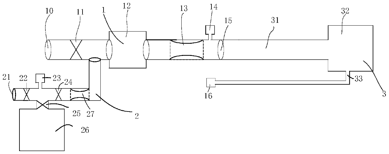
[0065] refer to figure 1 , the present embodiment provides a respiratory support equipment airway, including:

[0066] The main air intake passage 1 includes a turbine 12 and an air outlet 10 of the main air intake passage. The air inlet end of the turbine 12 is provided with a first on-off valve 11 for controlling air on-off, and the front end of the air outlet 15 of the main air intake passage is provided with Air outlet pressure sensor 14;

[0067] Oxygen intake channel 2 includes a high-pressure oxygen intake port 21 and an air storage bag 26. The end of the high-pressure oxygen intake port 21 is provided with a second on-off valve 22 for controlling the on-off of high-pressure oxygen, and the air storage bag 26 is located behind the second on-off valve. At the end, the air storage bag 26 is connected in parallel to the oxygen intake passage 2 through the third switching valve 25;

[0068] The breathing mask ...


PUM


Abstract

The invention provides a breathing support equipment airway and a safety control system and a control method. The breathing support equipment airway comprises: a main air inlet passage, a reserve airinlet passage and a breathing mask, wherein the main air inlet passage is connected with the reserve air inlet passage in parallel and is respectively connected with the breathing mask; a front end ofan air outlet of the main air inlet passage is provided with an air outlet pressure sensor; the breathing mask comprises a mask body, the mask body is provided with a pressure collecting port, and the pressure collecting port is provided with a mask pressure sensor. The control method of the breathing support equipment safety control system is also provided. A processor module, a turbine module,a pressure sensor and a power module of the breathing support equipment safety control system are respectively provided with a backup module, so that the processor module, the turbine module, the pressure sensor and the power module not only can work jointly, but also can work independently to complete an air supply function. When one of the modules fails, the other module can replace the work ofthe current module, maintain an output pressure of the breathing support equipment, maintain a user's normal breathing, and ensure the user's life safety.

Description

technical field [0001] The invention relates to the technical field of medical equipment manufacturing, in particular to a respiratory support equipment airway and safety control system and control method. Background technique [0002] In the field of medical respiratory support equipment (such as ventilator, high-flow respiratory humidification therapy instrument), respiratory support equipment, as one of the life support equipment, should have stable working performance, even if one of the functional modules fails, it should be able to degrade When using it, the phenomenon of stopping the gas supply cannot occur, ensuring the safety of personnel. [0003] The working principle of the respiratory support equipment with turbine air supply is: the processor of the respiratory support equipment controls the turbine speed to reach the pressure set by the user by collecting the pressure at the patient end. Existing medical respiratory support equipment is composed of various fu...

Claims


Application Information

Patent Timeline
IPC IPC(8): A61M16/00A61M16/06A61M16/12
CPCA61M16/0003A61M16/024A61M16/06A61M16/1005A61M16/12A61M2016/0027A61M2205/18
Inventor 戴征王磊
Owner HUNAN MICOME ZHONGJIN MEDICAL SCI & TECH DEV CO LTD
Why Eureka
Try Eureka