
Novel plate type air pre-heater

An air preheater and plate heat exchange technology, which is applied in lighting and heating equipment, combustion methods, indirect carbon dioxide emission reduction, etc., can solve the problems of high manufacturing cost, dust accumulation life, aging, etc., and achieve easy modular assembly, The effect of high plate forming rate and simple manufacturing and processing

Pending Publication Date: 2019-11-19
NANJING TONGCHENG ENERGY SAVING & ENVIRONMENTAI PROTECTION EQUIP RES INST CO LTD
View PDF0 Cites 0 Cited by
  • Summary
  • Abstract
  • Description
  • Claims
  • Application Information

AI Technical Summary

Problems solved by technology

[0004] The purpose of the present invention is to overcome the narrow application range, complex processing technology, high manufacturing cost, low pressure and temperature resistance of the traditional plate air preheater, and the phenomenon of aging during use, which is not suitable for the exchange of flue gas and air. Disadvantages such as heat transfer process, as well as problems such as traditional rotary and tube air preheaters are prone to failure, large footprint, low heat transfer coefficient, dust accumulation and short life; provide a new type of plate air preheater, the The air preheater forms the fluid channel of the heat exchanger through the support formed by the circular groove, and the opposite sides of the plate form a folded edge, which is easy for laser welding; the plate is a square structure, which is easy to modularize and assemble. The side is similar to a flat channel, and the groove formed by stamping on the plate increases the air turbulence without increasing the pressure drop on both sides, so the heat transfer coefficient is high and the pressure drop; in addition, the new plate air preheater has pressure resistance , heat resistance, simple processing and convenient laser welding, low manufacturing cost

Method used


Image

  • Novel plate type air pre-heater
  • Novel plate type air pre-heater
  • Novel plate type air pre-heater

Examples


Embodiment 1

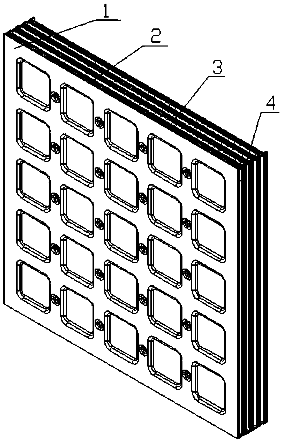
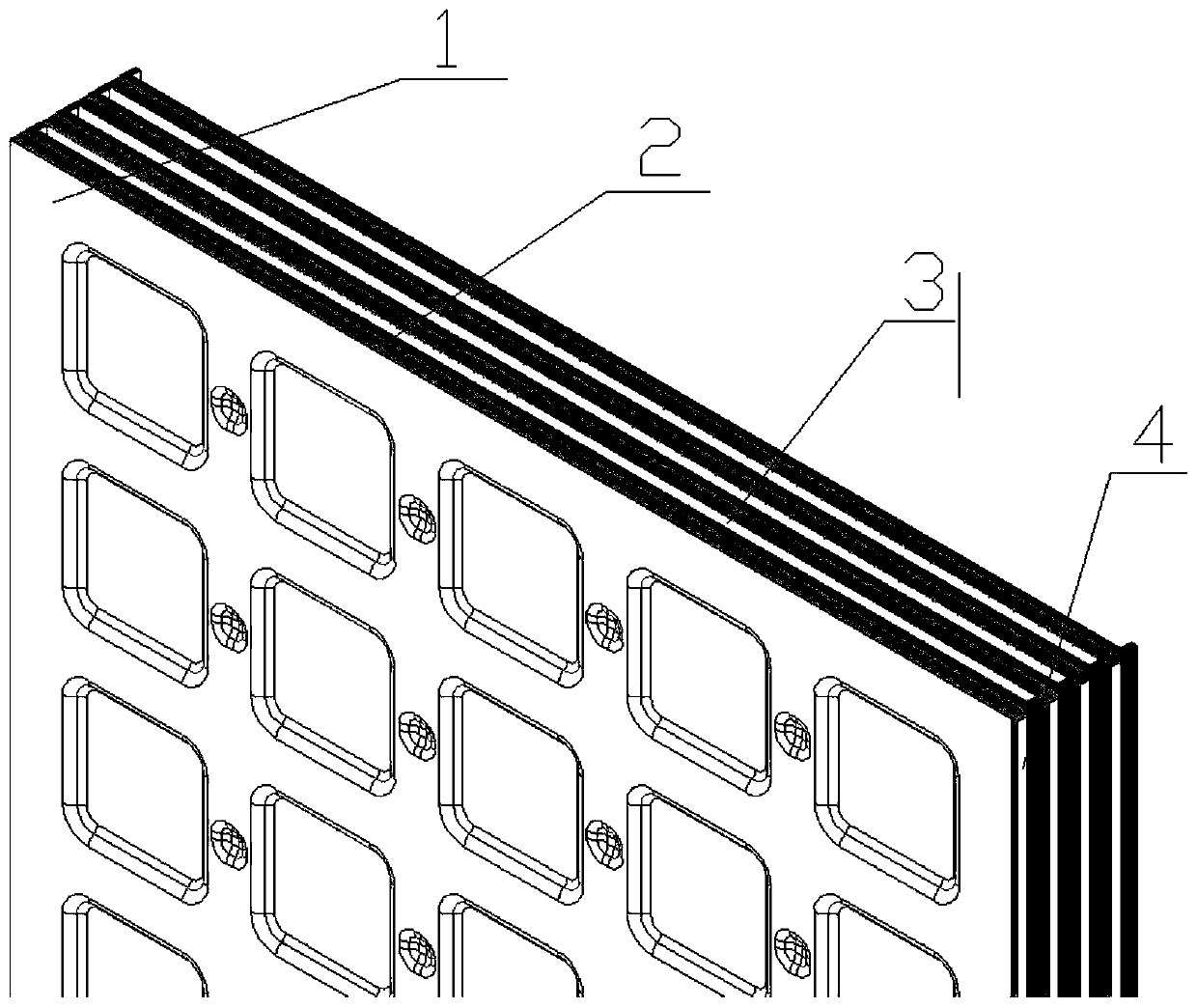
[0024] Embodiment 1: refer to figure 1 and figure 2 , a new type of plate-type air preheater, including: a plate-type heat exchange core 1 is formed by pressing a plurality of plates 2 that are stacked and welded at 90°, and the flue gas side is folded at 6 places to form a flue gas channel 3; the air side The folded edge 5 is welded to form the air channel 4 .

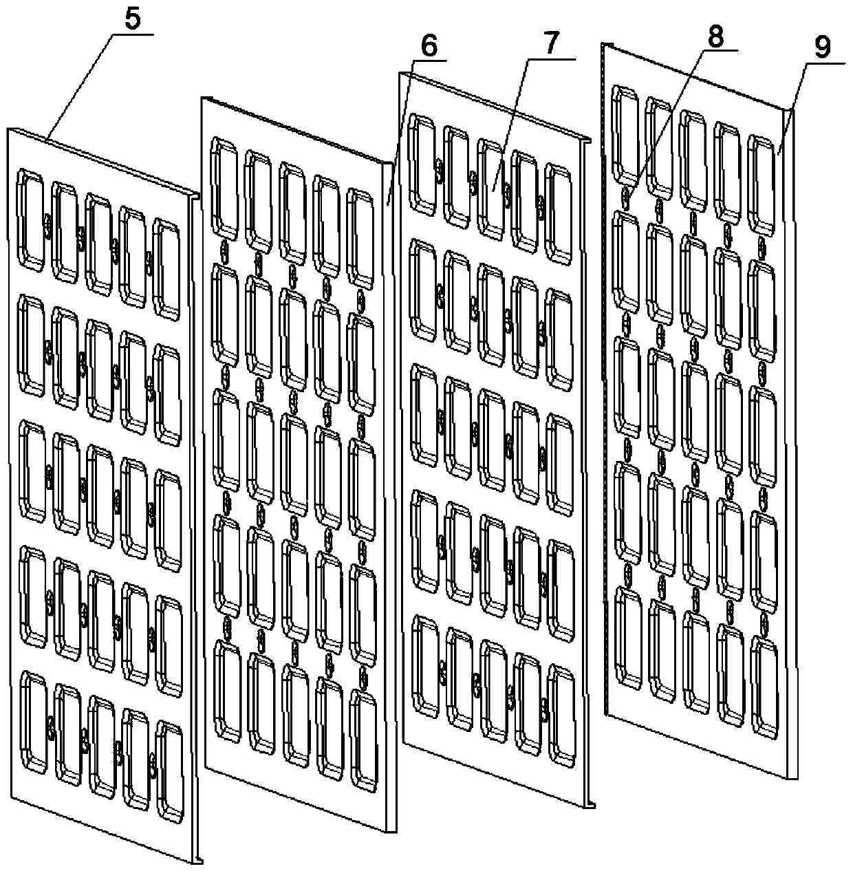
[0025] refer to image 3 , the two plates 2 formed by pressing are stacked and welded, and the stacking method is the overlapping of the quasi-circular groove 8 and the plane area 9 .

[0026] refer to Figure 4 and Figure 5 , There are pressed square grooves 7 and circular grooves 8, air side folds 5 and smoke side folds 6 on a single sheet.


PUM


Abstract

Provided is a novel plate type air pre-heater. A plate type heat exchanging core body is formed by a certain number of heat exchanging plates in a stacking manner; each heat exchange plate is formed by pressing a flat plate and square grooves and small round grooves between the square grooves are formed in the plate; a pair of edges are overturned; one of the heat exchanging plate pieces rotates by 90 degrees to be stacked with another heat exchanging plate at a certain interval; the square grooves are opposite to the square grooves; the small round grooves in the two heat exchanging plates are spaced by supporting plate pieces so that a channel height can be formed; after folding edges are welded, a fluid channel is formed; and two kinds of fluid are in cross flow according to the flowingmanner. The novel plate type air pre-heater is applicable to the field in which work media are clean, the air volume is large, the pressure drop requirement is low, and the heat exchanging requirement is high. A heat exchanging flow channel is similar to a flat plate channel, the grooves formed on the plate pieces due to stamping do not increase the pressure drop on the two sides while air turbulence is increased, and therefore a heat exchanging coefficient is high, and the pressure drop is low; and besides, the heat exchanger is resistant to pressure and temperature, machining is easy, edgestrips are not needed during channel welding, laser welding is facilitated, and the manufacturing cost is low.

Description

technical field [0001] The invention belongs to the heat exchange field of gas boiler waste heat recovery and energy-saving equipment, and in particular relates to a novel plate-type air preheater. Background technique [0002] At present, the recovery of flue gas waste heat in power plants is mainly realized through air preheaters, and the existing air preheaters are mainly rotary, tube and finned tube types. At present, in the category of gas boilers, tube air preheaters occupy a considerable proportion. Tube type and finned tube air preheaters have low heat transfer efficiency, large volume, easy to accumulate ash and are difficult to dispose of after ash accumulation, and the heat exchange tubes at the flue gas inlet are relatively worn, which affects the working efficiency and life of the air preheater. [0003] The plate heat exchanger has a compact structure and high heat transfer efficiency, but the processing technology is complicated, the manufacturing cost is hig...

Claims


Application Information

Patent Timeline
IPC IPC(8): F23L15/04
CPCF23L15/04Y02E20/34
Inventor 吴俐俊邱长亮
Owner NANJING TONGCHENG ENERGY SAVING & ENVIRONMENTAI PROTECTION EQUIP RES INST CO LTD
Learn More