Resin material chip-free cutting equipment and cutting method thereof

A technology of resin materials and cutting equipment, which is applied in metal processing and other directions, can solve the problems of low cutting precision and low cutting efficiency, achieve the effects of improving cutting precision, smooth cutting surface, and avoiding low cutting efficiency

Active Publication Date: 2019-11-22
漳州市澳捷光学科技有限公司
View PDF11 Cites 1 Cited by
  • Summary
  • Abstract
  • Description
  • Claims
  • Application Information

AI Technical Summary

Problems solved by technology

[0004] In order to overcome the above-mentioned defects of the prior art, the embodiment of the present invention provides a resin material chipless cutting equipment and its cutting method, through which the resin workpiece is melted and cut through the cutting assembly, and no debris is generated during the cutting process, thereby effectively ensuring The quality of the surrounding environment, while effectively preventing damage to the health of surrounding staff, effectively reducing the probability of staff suffering from occupational diseases, and effectively avoiding the problems of low cutting efficiency and low cutting accuracy caused by manual calibration in the prior art through calibration components

Method used


Image

  • Resin material chip-free cutting equipment and cutting method thereof
  • Resin material chip-free cutting equipment and cutting method thereof
  • Resin material chip-free cutting equipment and cutting method thereof

Examples


Embodiment 1

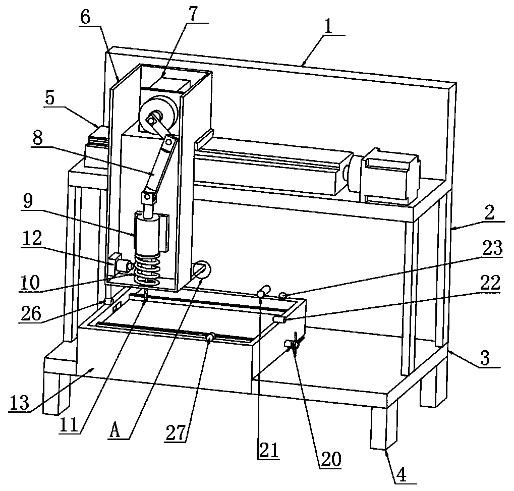
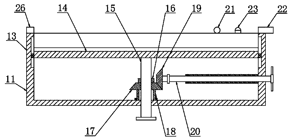
[0036] The present invention provides a chipless cutting equipment for resin materials, comprising a support base 1, a base plate 3 is provided at the bottom end of the support base 1, four columns 2 are fixed between the support base 1 and the base plate 3, and the support base 1 The seat 1 and the bottom plate 3 are fixedly connected by four uprights 2, the four corners of the bottom of the bottom plate 3 are fixed with support legs 4, the top of the support seat 1 is provided with a cutting assembly, and the top of the bottom plate 3 is provided with a calibration assembly. The above-mentioned calibration component is arranged under the cutting component;

[0037] The cutting assembly includes a linear guide rail 5, the linear guide rail 5 is located at the top of the support base 1, the linear guide rail 5 is fixedly connected with the support base 1, the top of the linear guide rail 5 is provided with a knife seat 6, and the knife base 6 Located at the front end of the su...

Embodiment 2

[0051] The present invention provides a chipless cutting equipment for resin materials, comprising a support base 1, a base plate 3 is provided at the bottom end of the support base 1, four columns 2 are fixed between the support base 1 and the base plate 3, and the support base 1 The seat 1 and the bottom plate 3 are fixedly connected by four uprights 2, the four corners of the bottom of the bottom plate 3 are fixed with support legs 4, the top of the support seat 1 is provided with a cutting assembly, and the top of the bottom plate 3 is provided with a calibration assembly. The above-mentioned calibration component is arranged under the cutting component;

[0052] The cutting assembly includes a linear guide rail 5, the linear guide rail 5 is located at the top of the support base 1, the linear guide rail 5 is fixedly connected with the support base 1, the top of the linear guide rail 5 is provided with a knife seat 6, and the knife base 6 Located at the front end of the su...

Embodiment 3

[0066] The present invention provides a chipless cutting equipment for resin materials, comprising a support base 1, a base plate 3 is provided at the bottom end of the support base 1, four columns 2 are fixed between the support base 1 and the base plate 3, and the support base 1 The seat 1 and the bottom plate 3 are fixedly connected by four uprights 2, the four corners of the bottom of the bottom plate 3 are fixed with support legs 4, the top of the support seat 1 is provided with a cutting assembly, and the top of the bottom plate 3 is provided with a calibration assembly. The above-mentioned calibration component is arranged under the cutting component;

[0067] The cutting assembly includes a linear guide rail 5, the linear guide rail 5 is located at the top of the support base 1, the linear guide rail 5 is fixedly connected with the support base 1, the top of the linear guide rail 5 is provided with a knife seat 6, and the knife base 6 Located at the front end of the su...


PUM


Abstract

The invention discloses resin material chip-free cutting equipment and a cutting method thereof, and particularly relates to the technical field of resin material cutting. The resin material chip-freecutting equipment comprises a supporting seat, wherein a cutting assembly is arranged at the top end of the supporting seat; the cutting assembly comprises a linear guide rail, the linear guide railis arranged at the top end of the supporting seat, a cutter holder is arranged at the top end of the linear guide rail, the cutter holder is arranged at the front end of the supporting seat, a motor is fixed inside the cutter holder, a crank rocker mechanism is arranged at the front end of the motor, a high-frequency induction coil is arranged at the bottom end of a linear bearing, the high-frequency induction coil is arranged at the bottom end inside the cutter holder, and a cutting needle head is fixed at the bottom end of the crank rocker mechanism. According to the equipment and method, the cutting assembly is used for melting and cutting a resin workpiece, chips are not generated in the cutting process, so that the quality of the surrounding environment is effectively ensured, the probability of suffering occupational diseases of people is effectively reduced, and the cutting efficiency and the cutting precision are effectively improved through a calibration assembly.

Description

technical field [0001] The present invention relates to the technical field of resin material cutting, and more specifically, the present invention relates to a resin material chipless cutting device and a cutting method thereof. Background technique [0002] At present, resin usually refers to an organic polymer that softens or melts after being heated. When softened, it has a tendency to flow under the action of an external force. Any polymer compound of the raw material is called a resin, and thin-plate resin materials include acrylic plates, nylon and PC lenses, and reinforced films. [0003] The equipment for cutting resin materials in the prior art usually uses a cutting knife, but when the cutting knife cuts, debris dust is also generated, and these debris dust floats into the air, which is easy to reduce the quality of the surrounding environment, and is easy to cause damage to the surrounding staff. Therefore, it is necessary to invent a chipless cutting equipment ...

Claims


Application Information

Patent Timeline
Patent Type & Authority Applications(China)
IPC IPC(8): B26F1/24B26D5/14B26D7/10B26D7/00B26D7/26
CPCB26D5/14B26D7/0006B26D7/10B26D7/2614B26F1/24
Inventor 吴国强
Owner 漳州市澳捷光学科技有限公司
Why Eureka
Try Eureka