
Water purifier with good noise reduction effect

A water purifier and noise reduction technology, applied in general water supply conservation, mechanical equipment, machines/engines, etc., can solve the problem of air not being discharged in time, and achieve the effect of stabilizing water flow, reducing impact vibration noise, and stabilizing water flow

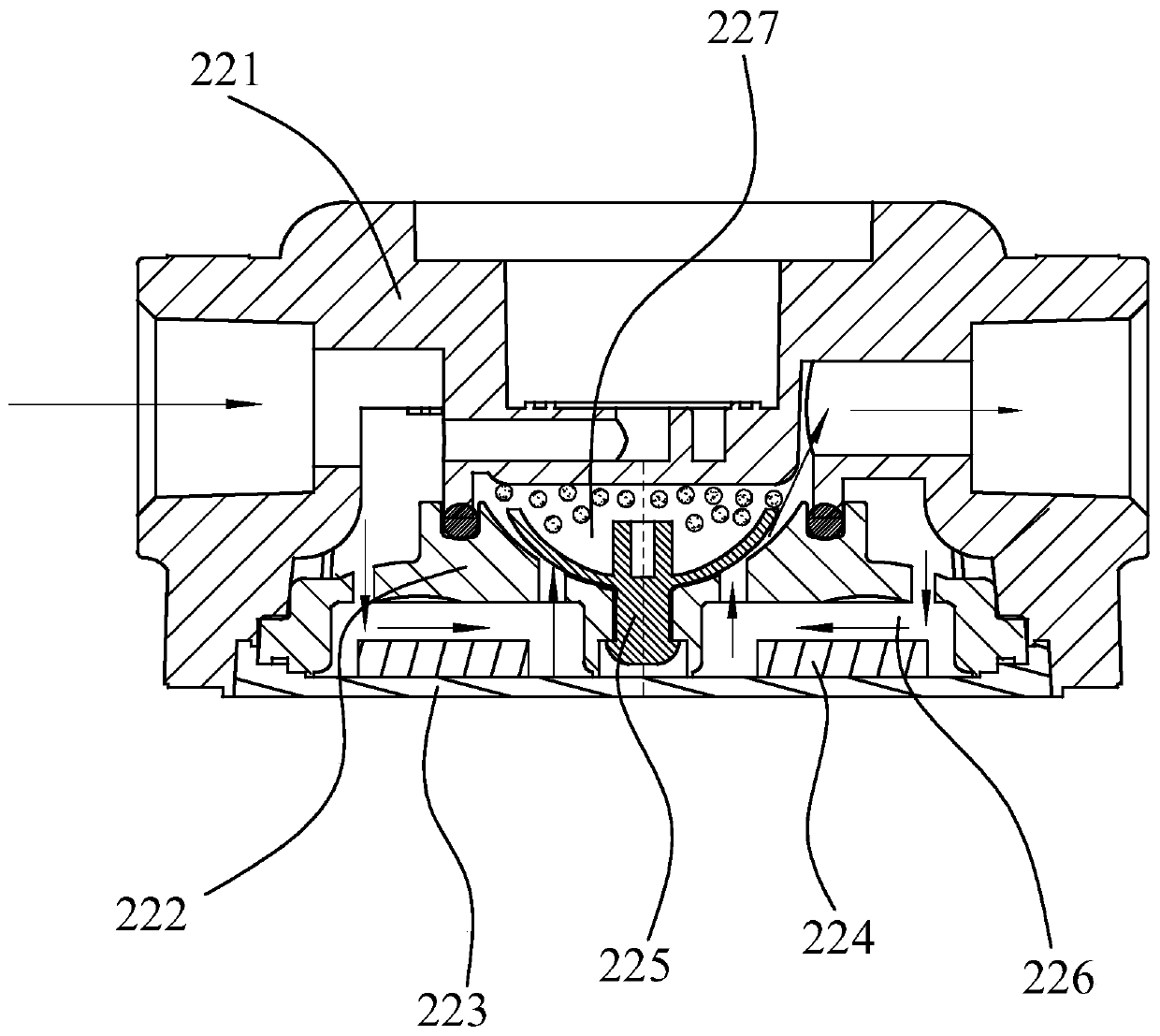
Active Publication Date: 2019-11-22
HONGYANG HOME APPLIANCES
View PDF7 Cites 0 Cited by
  • Summary
  • Abstract
  • Description
  • Claims
  • Application Information

AI Technical Summary

Problems solved by technology

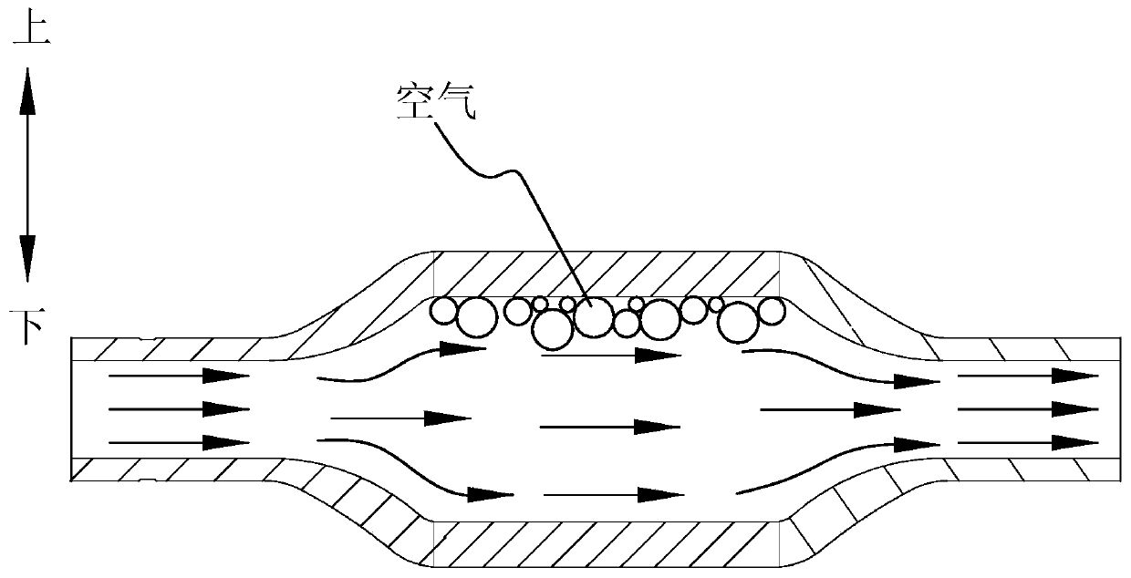
However, dampers in the prior art are usually placed horizontally, such as figure 1 As shown, when the water intake is started, the water in the buffer space is continuously converging. Due to the relatively fast flow rate of the water flow, the air in the upper part of the buffer space cannot be discharged in time. secondary noise

Method used


Image

  • Water purifier with good noise reduction effect
  • Water purifier with good noise reduction effect
  • Water purifier with good noise reduction effect

Examples


Embodiment 2

[0060] Such as Figure 9 , 10 , 11, the difference between this embodiment and the first embodiment is that the buffer chamber 430 includes a hollow chamber 431 and a water passage chamber 432, and the hollow chamber 431 is arranged on the outer periphery of the water passage chamber 432. Specifically, the housing 480 of the noise reducing element 400 corresponding to the water inlet chamber 420 , the buffer chamber 430 and the water outlet chamber 450 is respectively provided with a water inlet section 481 , a buffer section 482 and a water outlet section 483 . Specifically, the buffer section 482 includes an inner shell 482a and an outer shell 482b, the inner shell 482a has the water passage cavity 432, the hollow cavity 431 is formed between the inner shell 482a and the outer shell 482b, and the hollow cavity 431 is ringed. Set on the outer periphery of the water chamber 432 .

[0061] By setting a hollow cavity on the outer periphery of the water cavity, the hollow cavit...

Embodiment 3

[0071] Such as Figure 12 , 13 As shown, the difference between the present embodiment and the first and second embodiments is that: the inner wall of the water inlet chamber 420 and / or the water outlet chamber 450 is provided with a spiral rib 421 .

[0072] The high-pressure fluctuating water flow out of the booster pump passes through the water inlet chamber. Under the diversion effect of the spiral guide ribs, the water flow close to the wall of the chamber first flows along the spiral direction, and then drives the water flow away from the wall surface, that is, close to the central axis, along the A steady flow is formed in the helical direction. Then when the water flow reaches the junction of the water inlet chamber and the buffer chamber, the water flow still flows spirally under the action of inertia, but because the cross-sectional area of ​​the chamber becomes larger and the flow rate of the booster pump is constant, the flow rate of the water flow further slows dow...


PUM


Abstract

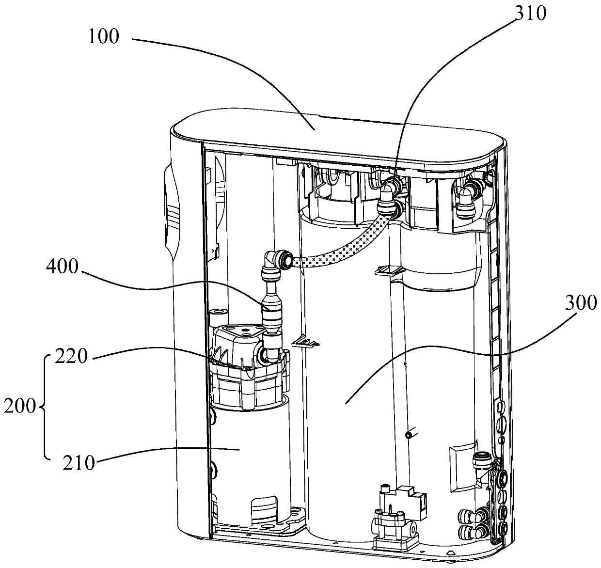
The invention relates to a water purifier with a good noise reduction effect. The water purifier includes a casing. A reverse osmosis filter element, a noise reduction element and a booster pump witha pump head are arranged in the casing. The booster pump is arranged upstream the reverse osmosis filter element. A water inlet and a water outlet are formed in the two ends of the noise reduction element respectively. The booster pump is vertically arranged, and the pump head is located at the upper end. The noise reduction element is vertically arranged downstream the booster pump, and the waterinlet is located at the lower end so as to reduce the water flow speed through water flow gravity. By the technical scheme, pulsation noise generated when air stays in the booster pump or the noise reduction element and collides with water flow can be reduced, meanwhile, the water flow speed can be reduced, stable water flow can be formed, and vibration and noise generated when the pulsating water flow impacts a pipeline are further reduced.

Description

technical field [0001] The invention relates to a noise reduction element, in particular to a water purifier with good noise reduction effect. Background technique [0002] A booster pump is usually arranged in the existing water purifiers to pressurize the tap water, so as to solve the problem of insufficient tap water pressure in some places in the prior art. However, the booster pump will form a pulsating water flow to impact the pipeline during the pumping process, so when the water purifier is working, it will generate large vibrations and cause noise, especially when working at night, affecting the user experience. [0003] After analyzing the vibration and noise source of the water purifier, the vibration noise mainly comes from the booster pump. Because the tap water is mixed with air, when the water enters the booster chamber of the pump head, due to the pressure change, the air resides in the booster pump. The cavity and collides with the water flow to produce a l...

Claims


Application Information

Patent Timeline
Patent Type & Authority Applications(China)
IPC IPC(8): C02F1/44F04B53/00
CPCC02F1/441F04B53/001Y02A20/131
Inventor 朱泽春刘博刘远马灿宏
Owner HONGYANG HOME APPLIANCES
Learn More