Fabric dyeing and drying system

A drying system and fabric technology, applied in the processing of textile materials, processing of textile material carriers, continuous processing of textile materials, etc.

Inactive Publication Date: 2019-11-22
孙艳敏
View PDF8 Cites 5 Cited by
  • Summary
  • Abstract
  • Description
  • Claims
  • Application Information

AI Technical Summary

Problems solved by technology

But this invention is not easy to import the cloth into the dye ...

Method used


Image

  • Fabric dyeing and drying system
  • Fabric dyeing and drying system
  • Fabric dyeing and drying system

Examples


specific Embodiment approach 1

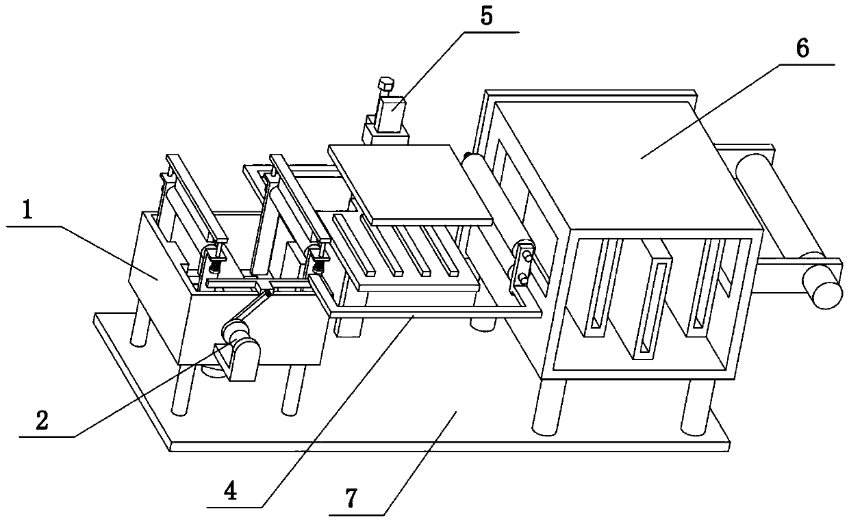
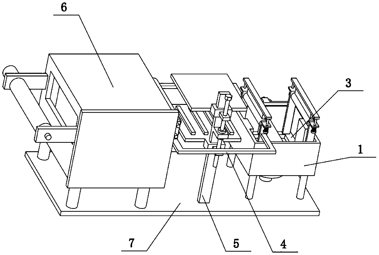
[0036] Combine below Figure 1-11 Describe this embodiment, the present invention relates to the field of fabrics, more specifically a fabric dyeing and drying system, including a dye box 1, a lifting frame 3, a bottom drum 302, a rotating seat plate 303, a riser 304 and an upper rotating Tube 309, the present invention can import cloth into the dye box 1 for printing and dyeing, and then export the cloth from the dye box 1.

[0037]The lifting frame 3 is slidably connected in the dye box 1, the upper four corners of the lifting frame 3 are fixedly connected with vertical plates 304, and the upper ends of the two vertical plates 304 at the left end are rotatably connected with an upper drum 309 , the upper ends of the two vertical plates 304 at the right end are rotatably connected with an upper drum 309, the front and rear ends of the upper middle part of the lifting frame 3 are fixedly connected with a rotating seat plate 303, and the two rotating seat plates 303 are rotatab...

specific Embodiment approach 2

[0039] Combine below Figure 1-11 To illustrate this embodiment, the fabric dyeing and drying system also includes a circular baffle 305, a convex plate 306, a spring sleeve rod 307, and a bead 308. On the upper side of the drum 309, the front and rear ends of the lower sides of the two beading bars 308 are fixedly connected with spring sleeve rods 307, and the upper ends of the four vertical plates 304 are fixedly connected with convex plates 306, and the four spring sleeve rods 307 are respectively slidably connected. On the four convex plates 306, the four spring sleeve rods 307 are sleeved with compression springs, the four compression springs are respectively located on the lower side of the four convex plates 306, and the lower ends of the four spring sleeve rods 307 are fixedly connected with round Blocking sheet 305 . The two beading bars 308 and the two upper drums 309 apply downward pressure respectively, so that when the cloth passes through the two upper drums 309...

specific Embodiment approach 3

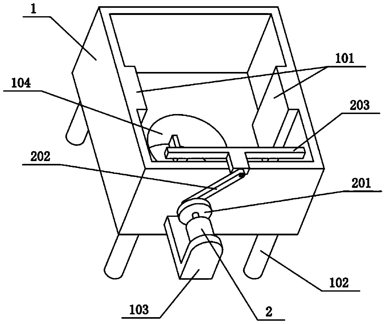
[0041] Combine below Figure 1-11 To illustrate this embodiment, the fabric dyeing and drying system also includes ribs 101 and rib grooves 301, ribs 101 are provided on the left and right inner walls of the dye box 1, and ribs 101 are provided on the left and right sides of the lifting frame 3. The convex groove 301, the two convex grooves 101 are slidably connected to the two convex grooves 301 respectively. The effect of setting the rib 101 and the rib groove 301 is that when the lifting frame 3 slides vertically in the dye box 1, the lifting frame 3 is more stable when it goes up and down.


PUM


Abstract

The invention relates to the field of fabrics, in particular to a fabric dyeing and drying system. The system comprises a dye box, a lifting frame, a bottom roller, rotating base plates, vertical plates and upper rollers; the system can guide cloth into the dye box for printing and dyeing and then guide the cloth out of the dye box. The lifting frame is slidingly connected into the dye box, the vertical plates are fixedly connected to the four corners of the upper side of the lifting frame, the upper rollers are rotatably connected between the upper ends of the two vertical plates at the leftend and between the upper ends of the two vertical plates at the right end respectively, the rotating base plates are fixedly connected to the front and rear ends of the middle of the upper side of the lifting frame, and the bottom roller is rotatably connected between the two rotating base plates.

Description

technical field [0001] The invention relates to the field of fabrics, in particular to a fabric dyeing and drying system. Background technique [0002] The application number is CN201811040543.0, which discloses an integrated production equipment for cashmere yarn dyeing and drying. The invention discloses an integrated production equipment for cashmere yarn dyeing and drying, including a dyeing vat. A transparent window is fixedly installed, a drainage pipe is sleeved on one side of the outer surface of the dyeing vat, a heat insulation frame is fixedly installed on the outer surface of the bottom end of the dyeing vat, and a bottom shell is arranged on the inner wall of the heat insulation frame. An electric heating rod is fixedly installed on the outer surface of the bottom shell, a support rod is fixedly installed on the outer surface of the upper end of the dyeing vat, and a drying box is arranged on the outer surface of the upper end of the support rod, and the outer s...

Claims


Application Information

Patent Timeline
IPC IPC(8): D06B21/00D06B3/20D06B23/04D06B23/20D06B15/00
CPCD06B3/201D06B15/00D06B21/00D06B23/04D06B23/205D06B2700/36
Inventor 孙艳敏
Owner 孙艳敏
Why Eureka
Try Eureka