Grid rudder unfolding and locking mechanism for spaceflight conveyer

A locking mechanism and grid rudder technology, applied in the direction of weapon types, projectiles, self-propelled bombs, etc., to achieve the effect of high locking rigidity, high locking rigidity and bearing capacity, and strong bearing capacity

Active Publication Date: 2019-11-22
SHANGHAI AEROSPACE SYST ENG INST
View PDF7 Cites 5 Cited by
  • Summary
  • Abstract
  • Description
  • Claims
  • Application Information

AI Technical Summary

Problems solved by technology

[0006] The invention aims to solve the problem of deploying and locking the grid rudder of the space transporter with controllable landing area, and provides a locking mechanism for deploying the grid rudder suitable for the space transporter with controllable landing area

Method used


Image

  • Grid rudder unfolding and locking mechanism for spaceflight conveyer
  • Grid rudder unfolding and locking mechanism for spaceflight conveyer
  • Grid rudder unfolding and locking mechanism for spaceflight conveyer

Examples


Embodiment Construction

[0034] The present invention will be described in further detail below in conjunction with the accompanying drawings.

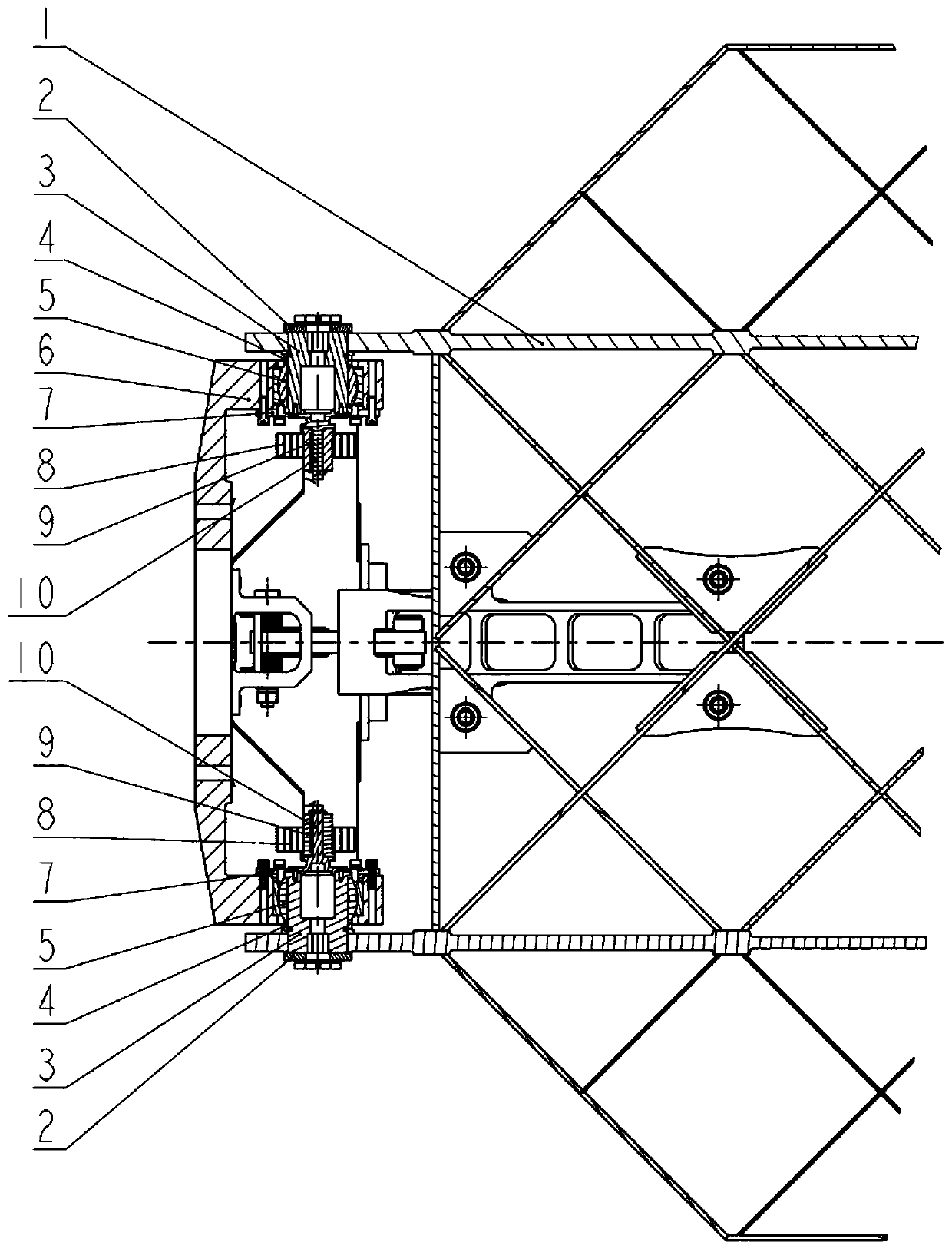
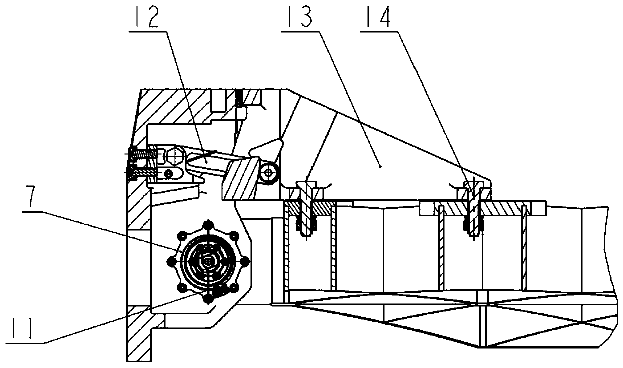
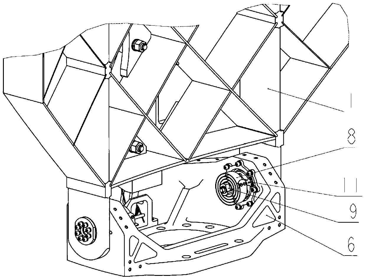
[0035] figure 1 and figure 2 It is a schematic diagram of the structural composition of the grid rudder deployment locking mechanism, image 3 and Figure 4 It is a three-dimensional schematic diagram of the grid rudder deployment locking mechanism. The mechanism consists of grid rudder 1, shaft end retaining ring 2, rotating shaft 3, washer 4, joint bearing 5, base 6, bearing end cover 7, plane scroll spring 8, spring inner end fixing part 9, spline shaft 10, spring The outer end fixing part 11, the locking rod assembly 12, the support rib 13, the connecting bolt 14, etc.; the base 6 is fixedly connected with the outer wall of the aerospace vehicle structure, and the grid rudder 1, the rotating shaft 3 and the inner ring of the joint bearing 5 pass through the washer 4. The shaft end retaining ring 2 is fixedly connected as one, and the outer ring of th...


PUM


Abstract

The invention discloses a grid rudder unfolding and locking mechanism for a spaceflight conveyer. The grid rudder unfolding and locking mechanism is characterized in that a plane volute spring is usedfor driving a grid rudder to be unfolded, a locking plane at the end part of a supporting rib is in cooperation with a locking plane on a base to realize forward locking through mechanical limiting,a locking rod component is in cooperation with a locking track surface in an inner cavity of the supporting rib to realize reverse locking through the self-locking principle. According to the mechanism, the grid rudder can be unfolded and locked by driving the folded grid rudder, the mechanism has the beneficial effects of being simple in structure, reliable in unfolding, high in locking rigidity,high in bearing capacity and the like, can be applied to unfolding and locking of the grid rudder of the spaceflight conveyer, and provides a technical guarantee for realizing the landing zone control and fixed point recovery of the spaceflight conveyer.

Description

technical field [0001] The invention relates to the technical field of aerospace transporter mechanisms, in particular to a grid rudder deployment locking mechanism suitable for a space transporter with a controllable landing zone. Background technique [0002] At present, my country's launch vehicles do not yet have the ability to control the landing zone of the sub-stage. The distribution range of the landing zone of the first sub-stage is generally 30 kilometers wide and 50-70 kilometers long. At present, more than 20 to 30 space launch missions are carried out every year, and tens of thousands of people need to be evacuated each time. The sub-level wreckage destroys houses, high-voltage lines, farmland, highways and other civil facilities, pollutes water sources, and brings safety to the lives and properties of people in the landing area. Serious harm and disruption of normal life and production order. In addition, it took a long time to search for and lose control of t...

Claims


Application Information

Patent Timeline
IPC IPC(8): F42B15/00F42B10/14
CPCF42B15/00F42B10/14
Inventor 宋佳袁伟顾珏华崔琦峰咸奎成陈雪巍金益辉秦伟沈蔚松
Owner SHANGHAI AEROSPACE SYST ENG INST
Why Eureka
Try Eureka